A Pull-Taut Hitch (for satellites!)

I apologize in advance for this monster post; I’m just trying to be thorough. I came up this knot several years ago for a very specific purpose, and at the time I searched this forum and several knotting books (obviously including the ABOK) and could not find it documented anywhere, so I think it might be original (but maybe I missed it or it was posted in the last ~3 years?).

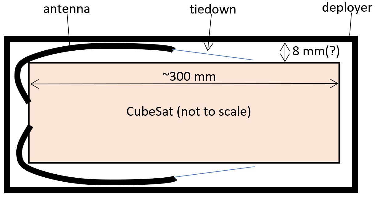
First, a longwinded backstory (feel free to skip to ‘Tying the knot’ if you don’t care about the ‘why’): This knot was developed to tie down the antennas of a CubeSat (low budget small satellites, roughly the size of a milk carton). On this and many other CubeSats, there are 4 antennas in a plus sign configuration at the bottom of the bus, and they are basically the spring steel that tape-measures are made of. To fit into the deployer, you bend the antennas back up against the body and tie them down. They are tied to a thermal knife (hot wire) that melts the line and allows the antennas to spring open once the CubeSat is deployed (see the diagram attached). The line had to be pulled tight enough such that the antenna did not bow more than a small distance off the surface and interfere with the deployer (something like 8 mm, but don’t quote me on that). We would then fully lock the knot with cyanoacrylate.

I want to stop here and note that there are a hundred ways to improve this antenna deployment method. I was not directly involved in the development of this particular satellite, I just volunteered to tie the knots because that’s my thing.

Normally, we would use monofilament nylon line to tie the antennas down. I was originally told this was because nylon slowly degrades in a vacuum, so if the thermal knife fails, the antennas will eventually deploy anyway due to… space. However, we got moved somewhat last minute to a launch deploying from the International Space Station (ISS) and would have to wait in a deployer outside the station for an extended period of time; so we had to use a material that does NOT degrade in a vacuum (so the antennas don’t pop open inside the deployer). So the team decided on Dyneema (HMPE). And not just Dyneema, but 6 lb. test fishing line Dyneema. It’s like trying to tie knots in a strand of hair. Even the famously secure Ashley’s Bend spills completely with little effort in this cord. (I was recently informed that nylon generally performs fine in space, so don’t quote me on the motivation for Dyneema. Either way, that’s what I had to work with.)

Furthermore, the line was epoxied at the antenna end, so if it broke or needed to be cut, we would have to remove the old line and wait for new epoxy to cure. Considering the team was way behind and fighting a deadline, this was not much of an option (the tiedown is one of the last things done prior to delivery). So I needed a knot that could be untied from ultra-thin Dyneema line (rather than cut) in case there were mistakes (and there would be - I believe this particular satellite actually had 8 tiedowns).

Here’s the main hurdle though: The (extensive) testing of the thermal knife was only done on a single pass of the line around the knife. Since everything going into space has to be rigorously tested, and using multiple passes was not, I was only allowed a single pass around the knife (e.g. even an extra round turn to take some of the load was apparently not an option).

As I said, there are a hundred better ways to do this, but this is what was handed to me, and this knot is what I came up with.

Since everything in aerospace has to have an acronym, we’ve referred to the knot in our lab as the Pull Antennas Taut Hitch, i.e. the PAT Hitch

No other pull taut knots that I could find worked for this situation, mainly due to the cordage, but also due to the requirement of being untieable or the fact that I only had maybe 3 inches of space between the antenna and the thermal knife to tie them. Of course, I investigated the trucker’s hitch, but it didn’t hold well and even an alpine butterfly as the pulley loop slipped in this cord (it also didn’t fit in the space given). The Pretzel hitch suggested on this forum (https://igkt.net/sm/index.php?topic=4464.msg36729) capsized and then slipped immediately (due to the cord). Friction hitches like the taut line hitch, adjustable grip hitch, Farrimond friction hitch, etc. could not be adequately pulled tight in this cord but were also dismissed because they were too big (the loop gets bigger as you tighten them, rather than smaller).

Tying the knot [reference number in pictures]

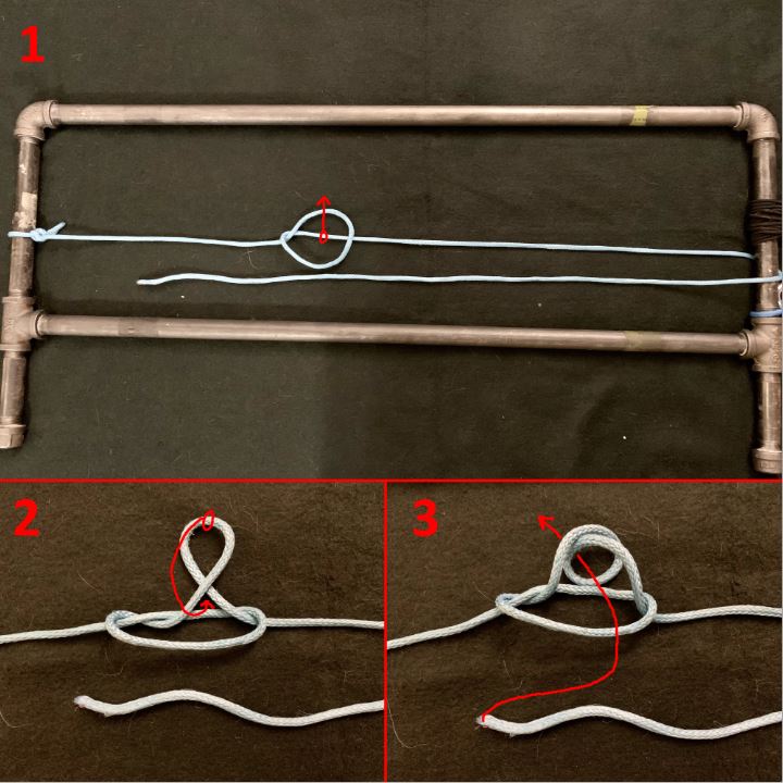
Step 1: Fix one end via your favorite hitch and loop the working end around whatever is to be pulled taut. Now form a marlinspike hitch structure: Take a bight of the standing end, give it a counterclockwise twist, and lay it over the rope towards the working end. [1]

Sidebar: I know it’s better to talk in terms of ‘sense’ or chirality, but I think [counter]clockwise twists are more intuitive to most. Here, a counterclockwise twist assumes you have pulled the bight toward yourself. Doing everything clockwise obviously works just as well, as long as you’re consistent.

Step 2: Pull a second bight up through the loop and give it another counterclockwise half twist. Now fold that twist down to invert it (doesn’t matter if you fold towards or away from yourself) and form a loop. This will form the collar around the working end. [2]

Step 3: Now this part is important, and I’m not sure how best to phrase it so pay attention to the picture. Relative to the initial marlinspike hitch structure, pass the working end through the collar from the side without the twist toward the side with the twist. Passing through the other direction will result in a knot that capsizes more easily. [3]

Alternatively, you can skip forming the loop in step 2 if you’re willing to pass the working end though the knot twice. Just pull the second bight up, pass the working end through, then loop it back towards itself and pass it through a second time. Pull the working end tight and the exact same structure will form. This can be an easier method in certain situations.

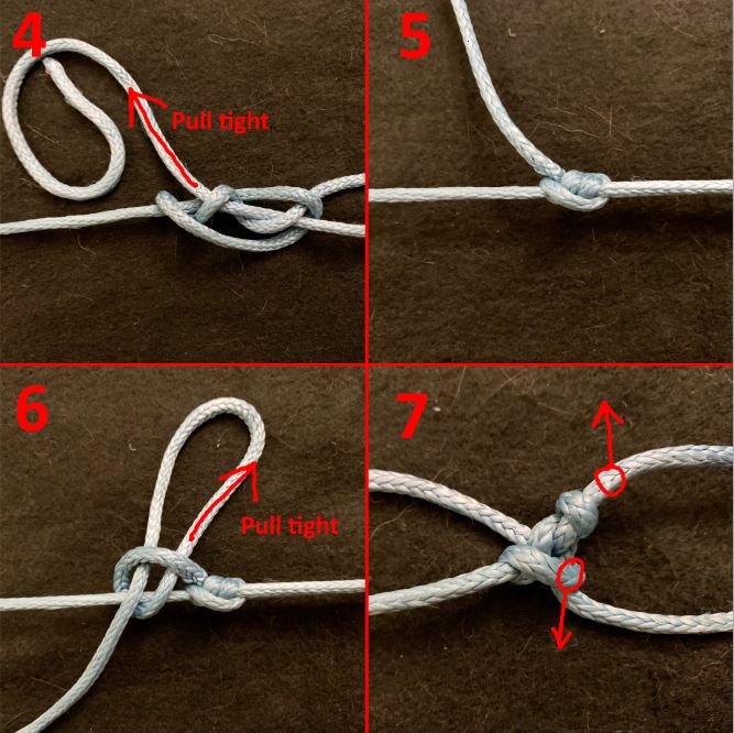
Step 4: Now simply pull the working end tight. [4] It often helps to pull a bit, let the knot settle, pull some more, etc. This allows the knot to properly tighten up on itself. On larger diameter ropes it can help to grab the knot itself with one hand and push it right (relative to picture) while you pull the working end left. [5]

Step 5: Finally, lock it with a half hitch or two. I usually just use one slipped half hitch. [6] Or for the case of sending it to space, I finished it with 3 half hitches and then a blob of cyanoacrylate.

To untie, first undo the half hitch, of course. Now, in small diameter Dyneema, for example, you can just pull the working end straight back through the knot in one go, then keep pulling and the knot structure will pop out of existence (this was the most attractive feature of the knot for the situation). In other cordage, my strategy is to hold the knot and pull as much of the working end as I can back through, then once I have a little bit of slack, pull up on the pre-knot working end and push down on the knot to try to yank the collar up and out of the knot. [7] Then you can pull the rest of the working end out more easily.

Additional info:

The knot was designed for small diameter Dyneema, but it works well in just about any rope. I use it all the time in paracord. I even use it in climbing rope to test climbing knots: I tie a new knot to my harness, then tie a PAT hitch up over my pull-up bar, and tighten myself up as high as I can so I can hang from it.

In developing this knot there were 3 main parameters I played with: 1. number of twists in the first loop, 2. the collar, and 3. direction the working end passes through the collar.

  1. I thought adding extra twists in the marlinspike hitch structure might make it a bit easier to untie (in the same way that a figure-8 is easier to untie than an overhand). It didn’t seem to make much difference and added complexity so I decided against it.
  2. For the collar, I tried no loop (just a bight), a round turn (shown here), 2 round turns, and a clove hitch. I also tried inverting and reversing the collars to see if that helped. No loop (i.e. just pulling up a bight and passing the working end through) actually works pretty well, but I found that it capsized more often. I think 2 round turns wound up bunching up on itself. The clove hitch just became a jammed-up mess. Ultimately, the single round turn seemed to perform best for my needs.
  3. Passing the working end through the knot in the direction shown here noticeably outperformed passing it through the other direction.
    I am certainly open to discussing these and other tweaks that might improve the knot.

I tried to get some numbers using my little knot tying rig and a crane scale. Using the smallest Dyneema cord I had handy (80 lb, 0.5 mm), I was able to secure a static 44.2 lb load in the line with the PAT hitch. In contrast, using an autolocking trucker’s hitch (with a directional figure-8), I was only able to get a 31.4 lb static load in the same cord.

“Long time listener, first time caller” situation. Open to constructive criticism and general feedback (format, writeup, pictures, etc.). Thanks for reading.


4-7.JPG

CubeSat.JPG

1-3.JPG

Hello ‘y0’ and thanks for your post.

I read everything a couple of times to make sure I understood what your main points are.
Just to make it easier for people to follow, I’ll try to extract the key points in point form:

  1. You are making a claim of originality.
  2. Your composite knot structure has a working title of ‘PAT hitch’.
  3. The ‘PAT hitch’ is tied from ‘dyneema’ (6 lb fishing line?)
  4. The purpose of the ‘PAT hitch’ is to hold tension in 6 lb fishing line - in order to secure a cube sat antenna
  5. Other candidate hitch structures slipped or could not hold tension in the ‘dyneema’ 6 lb fishing line material - only the ‘PAT hitch’ successfully held tension.
  6. Overall length from bearing point to bearing point (BP-to-BP) is approximately 3 inches (76.0 mm) - this is the dimensional space for the entire ‘PAT hitch’.
  7. Epoxy adhesive is used to cement/secure the terminating SPart to the antenna.

Additional parameters:

So I needed a knot that could be untied from ultra-thin Dyneema line (rather than cut) in case there were mistakes
Are we to understand that it is a requirement that the hitch structure must be [i]jam proof [/i]- ie, be untiable by hand?
Sidebar: I know it's better to talk in terms of 'sense' or chirality, but I think [counter]clockwise twists are more intuitive to most.
I respectfully disagree. Once you understand chirality (handedness) - it is easy and does not require a reference frame (a clock face requires a reference frame). The loop you created within the Marlinspike hitch is 'S' chirality. I would surmise that a 'Z' loop should also be effective? Your Marlinspike hitch is also 'S' chirality (hold it adjacent to a plane mirror and the reflected image you see will be opposite 'Z' chirality).
Using the smallest Dyneema cord I had handy (80 lb, 0.5 mm), I was able to secure a static 44.2 lb load in the line with the PAT hitch. In contrast, using an autolocking trucker's hitch (with a directional figure-8), I was only able to get a 31.4 lb static load in the same cord.
Interesting results... difficult to know with precision the geometry of your 'auto-locking' truckers hitch. Was your test rig vertically oriented (or horizontal)? Were you loading directly to your 'crane scale' or were you suspending a separate mass (vertical orientation) and using the crane scale to measure the force held?

Commentary:
The novelty is the way you have modified the Marlinspike hitch to act as a progress capture mechanism (to hold tension in a line).
The addition of a 360 degree turn to the ‘bight’ appears to enhance the ability of the Marlinspike hitch to cinch and hold the tail (so it doesn’t slip through).

The geometry/arrangement of the hitch is essentially a noose.
The modified Marlinspike hitch makes the ‘eye’ of the noose adjustable - but non-slipping.
NOTE: A regular noose structure slips/collapses (like a hangmans noose) - it does not hold tension.
Your ‘PAT hitch’ is an adjustable noose - it holds tension.

Due to the dimensional space limitation of 76.0mm (BP-to-BP) - the adjustable ‘eye’ must shrink in size (not increase in size).
This is interesting because many other adjustable noose hitches adjust along the SPart (standing part) rather than the tail.
See for example the Gnat noose hitch here: https://notableknotindex.webs.com/gnathitch.html
It is also an adjustable noose hitch - but the ‘eye’ increases in size as tension is increased (which is the opposite of your presentation).

As for your claim of ‘originality’ - obviously the Marlinspike hitch has been known and used for centuries - you have adapted it by adding a 360 degree turn to enhance gripping.
Using the Marlinspike hitch as a progress capture mechanism is what may be novel (or ‘new’).

As with all claims of originality, only in the fullness of time can it be established whether or not your claim is valid (or not).
It is not uncommon for claims to be later identified as ‘re-discoveries’ (as history has shown us with knots such as #1425A ‘Riggers bend’ and many other claims).
Just need to be patient and time will tell…

Hello! Thanks for the reply and thanks for reading it multiple times (I’m truly sorry for that).

3. The 'PAT hitch' is tied from 'dyneema' (6 lb fishing line?) 4. The purpose of the 'PAT hitch' is to hold tension in 6 lb fishing line - in order to secure a cube sat antenna 5. Other candidate hitch structures slipped or could not hold tension in the 'dyneema' 6 lb fishing line material - only the 'PAT hitch' successfully held tension. 6. Overall length from bearing point to bearing point (BP-to-BP) is approximately 3 inches (76.0 mm) - this is the dimensional space for the entire 'PAT hitch'. 7. Epoxy adhesive is used to cement/secure the terminating SPart to the antenna.
That is all the very specific situation for which the knot was developed, but it seems to work very well in general when you need to pull a taut line between two anchor points with synthetic cord.
Are we to understand that it is a requirement that the hitch structure must be jam proof - ie, be untiable by hand?
Yes, that was key. Even an overhand knot would have been virtually impossible to untie in the 6 lb test line, and in the event of a mistake, I likely would have been forced to cut the line and re-epoxy a new one to the antenna, which would have been an ill afforded setback.
Interesting results... difficult to know with precision the geometry of your 'auto-locking' truckers hitch. Was your test rig vertically oriented (or horizontal)? Were you loading directly to your 'crane scale' or were you suspending a separate mass (vertical orientation) and using the crane scale to measure the force held?
The auto-locking trucker's hitch was more or less what's shown here: https://www.youtube.com/watch?v=oNsuvZOI-0U The test rig was horizontal (most of it shown in the frame "1" above) and I was loading directly to the crane scale. I've also have attached some pictures of the tests to which I was referring.
As for your claim of 'originality' - obviously the Marlinspike hitch has been known and used for centuries - you have adapted it by adding a 360 degree turn to enhance gripping. Using the Marlinspike hitch as a progress capture mechanism is what may be novel (or 'new').
Yes, but I just used the example of the marlinspike hitch structure as an easy method to describe the first step of tying. I would argue the PAT hitch differs from the marlinspike hitch in the same way that a double bowline differs from a sheet bend. They of course do share structural similarities.

Hello ‘y0’,

Looks like no one else has replied or offered any commentary on your ‘PAT hitch’.

As stated, this is a variation of the existing Marlinspike hitch (#559).
You have simply added a 360 degree turn to the bight segment.

What is novel is the way in which it is employed.
It is employed as a progress capture device.
Of interest to me is the fact that adjustment of the ‘eye’ is done by drawing the tail end through the modified Marlinspike hitch.
In this configuration, as the eye is shrunk, the overall line length decreases (and there is a corresponding increase in line tension).
Usually, the opposite occurs with regular noose structures.
That is, in a typical noose configuration, in order to increase line tension, the ‘eye’ increases in size.
In your configuration, in order to increase line tension, the ‘eye’ decreases in size.

I therefore like the way in which you have solved the problem of working within very limited space.
Your progress capture device works effectively within the limited space of the satellite containment vessel.

With specific regard to your comment:

I would argue the PAT hitch differs from the marlinspike hitch in the same way that a double bowline differs from a sheet bend. They of course do share structural similarities.
Yes - #1010 and #1013 are both 'Bowlines'. There are numerous different types of 'Bowlines' - all with various geometric forms. So yes - a good analogy.

I personally have never seen a composite knot structure configured in the manner you have presented.
Using the #559 Marlinspike hitch as a progress capture device is novel and ‘new’ (as far as I can determine).
The addition of a 360 degree turn increases gripping surface area contact - preventing the thin ‘dyneema’ line from slipping.

As for your assigned name:

Pull Antennas Taut Hitch, i.e. the PAT Hitch
Or perhaps: 'Marlinspike Antenna Capture' hitch (MAC hitch).

Ha, we need to replace this term with “loosenable”! :wink:

The auto-locking trucker's hitch was more or less what's shown here: https://www.youtube.com/watch?v=oNsuvZOI-0U
Aha, at first this seemed to have instantiated the so-named "Gleipnir", floating-binder mechanism that I've done for some various things. But on close showing, this fellow's structure is more nearly a sort of [i]blackwall / Garda hitch[/i] --in the hauling line through an eye!

What I’ll recommend you try, thus, is much the same structure
in large, but get it so that the eye makes the gripping turns
such as you put into your knot, through which the haul line
is pulled; to effect this smoothly will require a stabilizing line
going through the nipping turns/coil as well --which, alas yes,
might too much defeat the gripping effect. :-\

So, sketched in general, oriented left<->right as you have
with that tubular/pipe frame :

  1. anchor line at left ;

  2. tie a bowline (BWL) --well, for starters and if it needs
    improvement, then a next-choice eye knot-- at whatever
    point in the span makes sense ;

  3. run the tail from the eye knot around one side of the
    an eye leg, wrapping the tail BUT THEN pulling tight on
    the tail to cast its wraps into turns of the eye;
    to which now might come some need for TLC to get this
    coil happy at existence AND loosEnuff to accommodate
    another strand passed though it …

  4. take the tail out around your opposite-anchor point
    (which I think is your thermal knife?!), and bring it
    back …

  5. … to reeve through that #3 coil from the opposite
    side it exited from earlier (this is the “stabilizing” aspect).

Now, I believe that you tightened your structure by pulling
away from knife towards anchor; HERE, you’ll pull in the
typical trucker’s hitch direction, away from anchor.
The harder the pull, the tighter the coil should bind on the
lines through it --hoping that it’s tight enough, given that
the two X-ing lines somewhat lessen the gripping that might
come upone one line alone.
But you need this tension only so long, before your additional
securing (further knotting, & glue?) is done, right?

As for your claim of 'originality', obviously the [i]MarlinEspike hitch[/i] has been known and used for centuries; you have adapted it by adding a 360 degree turn to enhance gripping. Using the [i]Marlinespike hitch[/i] as a progress capture mechanism is what may be novel (or 'new').
Yes, but I just used the example of the [i]marlinespike hitch[/i] structure as an easy method to describe the first step of tying. I would argue the [i]PAT hitch[/i]differs from the [i]marlinespike hitch[/i] in the same way that a [i]double bowline[/i] differs from a [i]sheet bend[/i]. They of course do share structural similarities.
And I've used a similar modification of this as a BWL base --seeing that nipping turn as key. And I've tried it from both directions : where the SPart makes the loop, and then where it makes the surrounding of that loop which itself is loaded from the eye (and in which form it's not much BWL).

If I’m remembering the images now, seems to me that your
hitch’s coil could maybe better go in the opposite direction?!
–yes, by which I mean the orientation of the loop as you have
before folding to double it, in your Fig.#2 :
the line comes in and loops,
rather than coming in but first arcing against
the surrounding part, into the coil.

Cheers,
–dl*

per Dan:
Just to add some clarity re the ‘truckers hitch’…
I think ‘y0’ only used a ‘truckers hitch’ to perform some break tests (ie pull right up to the materials MBS yield point).
Within the actual satellite deployer, the dimensional space is very limited.
‘y0’ indicated that his line tensioning system had to fit within a 3 inch space (76mm) - as measured from bearing point to bearing point.
So I think ‘y0’ was not able to use an actual truckers hitch due to space limitations - that is, the limited space is a key driver for the choices he made?
‘y0’ would need to confirm this limitation?
It also appears that in his MBS break tests, the ‘truckers hitch’ did not achieve favorable results?

Now, I believe that you tightened your structure by pulling away from knife towards anchor; HERE, you'll pull in the typical trucker's hitch direction, away from anchor.
Again - I believe that 'y0' made a design choice to pull [i]away [/i]from the thermal lance due to the dimensional space limitation of 3 inches (76mm). This I believe is the 'new' or 'novel' use of the modified Marlinspike hitch - for which he is making a claim of originality.

Dan:
Can you directly comment on his claim of originality?
Whilst the #559 Marlinspike hitch isn’t ‘new’ - the manner in which he has modified and employed that hitch to function as a ‘progress capture device’ may be regarded as ‘new’ or novel.

Also, with your suggestion to use an alternative tensioning system based on a ‘Bowline’ (#1010?)… with regard to your steps 1-5, this may be hard to interpret and follow as you intend… any chance of photos?

I think 'y0' only used a 'truckers hitch' to perform some break tests (ie pull right up to the materials MBS yield point).
I was not testing breaking strength, but yes, the test above was simply seeing how much tension the Pat Hitch would hold relative to "the next best thing". Note: the 80 lb. figure was just the MBS reported on the packaging of the cord I used, and it seems to have outperformed its quoted strength. Also note the crane scale was attached to the rig by a couple dozen loops of shock cord to add a little give to the system. I just pulled on the Pat Hitch and let go a few times and it would slip a little at first but managed to catch itself and hold steady at 44.2 lbs. Whereas with the "auto" trucker's hitch, I was pulling and actively doing my best to pinch/assist the autolocking mechanism to hold as much tension as possible while I locked it with a half hitch; and I still only managed to get 31.4 lbs. in the line.
Within the actual satellite deployer, the dimensional space is very limited. 'y0' indicated that his line tensioning system had to fit within a 3 inch space (76mm) - as measured from bearing point to bearing point. So I think 'y0' was not able to use an actual truckers hitch due to space limitations - that is, the limited space is a key driver for the choices he made? 'y0' would need to confirm this limitation?
Correct, the trucker's hitch was not an option for the antenna tiedown for a variety of reasons. First, the space limitation. Second, it would be very difficult to hold tension in the tiny cordage while tying the locking half hitches. Third, any "pulley" midline loop I could think of would either slip or risk jamming (again, this ultra small cord was a nightmare).

Sidebar: it would seem I chose an awkward user name, given how often it appears in quotes haha. I thought I was being clever a couple years ago… y[subscript]0, pronounced by, say, a physicist as “y-naught” or, you know, “why knot”… I’ll see myself out ;D
Maybe I’ll change it while I’m still relatively new :slight_smile:

Also, with your suggestion to use an alternative tensioning system based on a 'Bowline' (#1010?)... with regard to your steps 1-5, this may be hard to interpret and follow as you intend... any chance of photos?
I also found this a bit difficult to follow; any clarification would be appreciated.