Best lashing knot for three perpendicular poles.
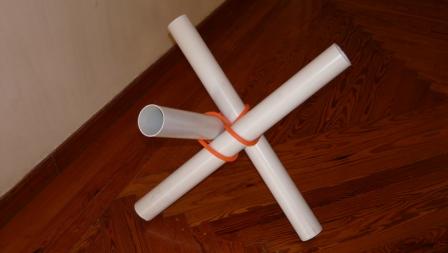
Best lashing knot for three perpendicular poles.
I’m no expert, but this tripod lashing (racking turns) works and is easy for me to remember:
http://www.ropeworks.biz/archive/tripod.html
“Bind three poles, in touch and perpendicular to one other, with one piece of rope, as tightly as possible.”
This above statement is what you are trying to accomplish?
Perpendicular: noun: a straight line at right angles to another line
adjective: intersecting at or forming right angles
They are the same size I assume, touching each other (no rope between them) and perpendicular to each other?
What will be the abstract purpose of these three poles?
Do they have to support themselves in this configuration or bear additional weight?
Or is this decorative?
Scott
The sticking point here for me is the need for the poles to be oriented Perpendicular to each other.
To me that means they are to be at right angles, 90 degrees to each other.
And if only the ends are to be joined the I see the need to “waste” cord with frapping turns.
Otherwise a knot is to be tied and then the parts of the affair rotated to induce a tightening twist.
The knot must have sufficient round turns to reduce the load(s) on the cord alleviating the strain on one small area.
If the knot is overtightened before the twist/reorienting is done then all bets are off.
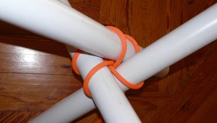
The attached is a fairly simple tripod style lashing that to me reduces the frapping turns.
S
SS, I don’t understand what’s going in step 3. Is there a better diagram?
Hi knot4u,
what is happening is the same as in doing the sail-makers whipping.
The cord is being roved between the poles to fill and tighten.
It is just an alternative to “standard” sheer lashing.
No I don’t have a better diagram at present, sorry.
i think people are getting confused by the perpendicular part. think of the corner of a table, one pole is one side, one is the other and the third is the leg . i e repeat 4 times to make your table frame. hope this helps
While we’re looking for a knot solution, I’m also interested in a solution for holding the poles in that position before the rope is applied.
If the practical application is heavy logs, which you mentioned above, then having the poles in the final position before tying the rope is already a difficult thing to do. For this pre-problem, I’m imagining some kind of support on each leg to hold each leg up at the appropriate angle. Based on your criteria that I quoted, you may have eliminated the option of tying two legs and then attaching the third. Or did you not mean to eliminate that option?
You have a nearly impossible problem. With heavy logs, the rope will have to overcome an extremely high moment of inertia on each leg. The tripod lashing may consume a lot of rope, but this contraption would consume way more rope to keep the legs stable.
Unless… You first carve out pegs and recipient holes in each leg. Fit the legs together so that they form the right angles as described. Then, apply the rope around the vertex such that the rope provides support to the pegs and holes. The pre-fitting will take strain off the rope. Even then, I think you’ll need additional support beams to support the three legs, like the cross beams at the top of this structure:
http://i56.tinypic.com/4qfyn4.jpg
By the way, rope is not the best solution to this problem, but we’re all playing along because that’s the parameters.
Well, yeah, but you just added more material. I thought the only material we had were the three legs and rope.
If we can add other materials, then your problem becomes trivial. You bind two legs on the ground at a right angle by using a cross beam and nails/bolts. Then, bind the third leg by using two more cross beams. You can add the rope, but it would be unnecessary. I have made this type of construction before. If you remove the crossbeams and have just rope at the vertex, then the structure becomes unstable. I wouldn’t use if for anything other than art.
Have you considered the Chinese bamboo scaffold solution?
http://darkwing.uoregon.edu/~struct/courseware/hk1/hk1_bamboo/bamboo_connection2.jpeg
Derek
A cloverleaf lashing (slightly adapted for non-parallel poles) would connect each pole to the other and maintain the symmetry of the joint. Tightening will need to be addressed for any method where the poles are to remain stationary during the entire process. Tourniquet methods may be of use for tightening? This topic falls under the category of “Pioneering” for those of us that are/have been involved in scouting.
DDK
You may have read more into my comment than I had intended. I certainly was not implying that this was only of interest to scouts nor was I suggesting that this knot problem would only arise for those engaged in Pioneering. As it happens, this problem has been addressed by several involved in Pioneering and their solution may be worth a look.
The cloverleaf lashing was developed to address the multiple attachment of poles at (or near) a single point. I have seen examples of 4, 5 and 8 pole attachments. For 3 poles, the attachment would be at a single joint (that is, each pole is intimately connected to the other two with the use of in total a single lashing).
DDK
No. You would have one (single) three pole binding knot (lashing). If one googles cloverleaf lashing, the first link to be listed has a description of this lashing
http://ropesandpoles.blogspot.com/2007/06/clover-leaf-lashing.html
DDK
Indeed, when the number of poles is 4 or more, I would also describe the cloverleaf lashing as a compound knot or multiple joint as it is clear that each pole is not directly connected to all the others. When the number of poles is 2 or 3, however, this is not the case and it is clearly not a compound knot, but a single binding. For the problem you posed, the number of poles is 3.
As I have mentioned in a previous post, the cloverleaf lashing would need adapted to non-parallel poles. One of these adaptations could be to have the poles in contact. To point out what may be obvious, one way to reverse-engineer the lashing for non-parallel poles would be to:
(1) Apply the round turns but not the fraps to 3 parallel poles.
(2) Spread the tripod to the orthogonal condition desired (there is a clockwise spread and an anti-clockwise spread - one will tend to tighten the lashing and the other will tend to loosen the lashing). I would speculate that the spread that loosens the lashing will be preferred in that the applications of fraps will be more effective at tightening the lashing.
(3) Observe the wrapping of the round turns.
(4) Develop a method for the application of the fraps and the tightening of the lashing.
I would assume that all of this has been accomplished a number of times by those that commonly use the cloverleaf lashing, however, I have not seen it reported.
To summarize what I believe to be true about the use of the cloverleaf lashing on 3 poles is this:
(1) The poles can be in contact, orthogonal and stationary prior to their binding.
(2) It will be a single binding.
(3) The lashing will have the same three-fold axial symmetry as the arrangement of the poles. This “cube-corner” symmetry is the same as found in the Monkey Fist, for example.
(4) The application of fraps for the purpose of tightening will be as effective as in most lashings.
DDK
My mistake - I thought the term reverse-engineering was fairly common and would be understood. It describes a process by which one may develop understanding and/or a new process from an existing process, for example. In this case, once one has easily discerned how the round turns are to be wrapped on stationary and orthogonal poles by spreading the tripod in the conventionally wrapped lashing of parallel poles, one forever knows how to apply the round turns from scratch to any set of stationary and orthogonal poles. So, in this “newly” developed process with this “new” information, the poles are in contact, orthogonal and stationary prior to the wrapping of any round turns or fraps. There is nothing at all farfetched about it.
DDK
I have been experimenting with this one a bit and besides the want of the poles to go everywhere except where I need them here’s the best method I’ve come up with to date.
However you can secure the three perpendicular poles in the correct orientation, do so.
Cut a suitable piece of accordingly sized cord/rope to length.
Starting with the “vertical” pole tie a double constrictor knot at location and tighten with the leads going around to the backside of the knot. Cross the leads back there. That should be the outside of the corner.
I originally tried Prusik, clove and Klemheist hitches and they work, just not as well.
Now position the additional poles to their respective perpendicular places above the dbl constrictor.
Take the two now crossed leads and go around the outside of the two crossed and touching poles guiding one cord into the each “V”. Now do one or two frappings around the V’s with both lines in opposite directions. This is all happening outside the vertical pole.
Finally take the leads under both horizontal poles and cross them while going up inside to the final position of over and outside the horizontal poles to be tied off with any number of binding knots. Though continuing to go around the unoccupied V (back) and then to tie off around the vertical pole will add some more spreading stability. to the whole thing.
The main thing is to have a dependable support knot on the main pole and then frapping turns that will cinch the two other poles snug to the main.
Looks like hell but it will freely hold the three poles.
Hope it makes sense. I see it so… muddily.
![]()
Oh yes, I agree wholeheartedly that the affair I have tangled lacks symmetry.
The first thought was to get the job done.
Next it was to minimize the amount of cord used without diminishing security.
Third is relative ease of tying. Which I don’t think I did either.
I believe the basic concept-design elements of what I did would be enhanced by additional round turns on each of the members and even then around all of them.
But that will use an awful amount of cord.
As for a “knot” doing this and doing it well, I think not.
Maybe you could do some kind of super duper go everywhere Pile hitch twisting,and yanking as she went.
What have you got?
???
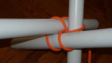
If this photo does not show the general relationships of the
“Bind three poles, in touch and perpendicular to one other”
problem you’re exploring, please explain why not, and what does.
To me, an essential element of reality is missing from the problem
statement --to wit, gravity : what bears load, in what direction!?
E.g., in Derek’s presented image, the vertical pole supports the
others bound to it, and one might bind the lower of these very
securely essentially just attach the 3rd one stop this support,
or one might bind the upper and essentially support the lower
via friction-hitch mechanics.
Hi, I just joined the forum and made my first post. By coincidence it is a solution to the problem posted in this thread. Xarax pointed this out. See http://igkt.net/sm/index.php?topic=2078.0