fiddling with a Poldo tackle

Were you also not able to TEST this theory?!

FYI, I now have 37.5# suspended at your point F
–downwards bearing (gravity) force at that point
on the lower internal sheave–,
and 25# as W :: there is no movement
–that is not “4:1”, 3:1, 2:1, 1.5:1, 1.1:1 even.

IF I attach some helper force (to use dead weight,
then a redirecting pulley will do, but will ameliorate
force via friction (roughly 0.66 per 'biner)), THEN one
can begin to raise the load. But one must add this
added weight to the already present 37.5 and of course
that takes it farther away from W=25#.

But people/authors can publish raves about the mysterious benefits
of these structures, over & over! (And the books, remember,
talk of pure rope-on-rope, nevermind even 'biners for help!)

–dl*

As we can see in the attached picture, in the “ideal” case, to just establish a state of equilibrium, and prevent an automatic maximal elongation / extension of the tackle by itself, we have to keep pulling, at all times, each of two points on two segments of it towards opposite directions, with a force equal to the 1/4th of the load ( see the purple arrows, labelled by the letter F).( Or we have to place a spring :slight_smile: in between those two points, to pull them towards each other with a force F … but then we will not be talking about a rope-made block and tackle mechanism any more, because those mechanisms do not store or use any induced energy ).Therefore, any gains we may have by utilizing its 4:1 mechanical advantage, are cut by half.

Correct. In the ideal case, you will really need that spring - or three, not-annihilated hands :slight_smile: : two hands to pull the two segments with a force equal to the 1/4th of the load, so the tackle remains in equilibrium and is not elongated / extended by itself, and, after you had established this equilibrium, one more hand to pull knotsaver s point P, and utilize the 4:1 mechanical advantage - which concerns only what is left if from the total load we subtract the 1/4th two times, that is, half of it !

There is no such 4:1 IMA !
Movement of rope from those indicated points
–nb: movement measured from final positions! (!?)–
Upwards & Downwards (indicating direction from
the points of contact) is respectively 1L & 0.5L
of a fully extended span of 3L (mid-point 1.5L)
with then double bearing (3 x 2 = 6L) of our ideal
6L of involved cord; the fully contracted (having
lifted Weight) system is 2L (x3 = 6L).
So, we move 1.5L to lift weight 1L :: 1.5 : 1, not 4:1.
Orrrr, am I mismeasuring here to count just rope --from
two moving points(!)-- and should count hand motion
(or, OTOH, rope attached to these points used qua haul lines),
in which case the Upwards movement goes from the
bottom/low sheave point to 0.5L from top,
netting 3-0.5 = 2.5L + 0.5L Downwards => 3:1 !?
(It sure doesn’t feel like this!)

But I’m hoping that someone out there can put highly efficient
–even, relatively efficient compared to 'biners-- PULLEYS into
such a system and then see what happens with actual weights
attached at various places. I think that the movements that
actually occur will be most interesting (as well as the weights
needed to get movement)!!
(I don’t have such pulleys. Maybe I can find those plastic-bottle
sheaves & associated cord with which I saw slow extension.)

–dl*

Iff you keep pulling the two lines at the points I have shown with force F equal to the 1/4th of the load ( so the tackle reaches the state of equilibrium, and remains there ), the mechanical advantage is 4:1.
You have not found any flaw in knotsaver s calculation. When you drag the line and move point P at a distance p, the load is moved at a distance p/4. ( knotsaver has calculated this when point P moves distance 3L upwards, and then distance 1L downwards, that is, a total distance of 4L - and, at the same time, the total length of the tackle goes from 3L to 2L, so its lower end point, and the load attached on it, is raised/lifted 1L. )
You can not “feel” the 4:1 mechanical advantage, because, at the same time you pull point P, you have also to pull points F, each one with a force to the 1/4th of the load.

Please look at the attached figure:
Suppose:

  • rope lenght = 15 L
  • pulley C blocked
  • force F (in red) applied as indicated
  • it doesn’t matter that second diagram is at max extension
  • lines have to be considered vertical
    For me these are the moves (tested moves):
    As the force F has been acting on the Poldo tackle, we have pulled the point P for a displacement of 4L in length whilst pulley B has moved (downwards) by 2L in length and the load (pulley A) was lifted only by 1L in length.

    (to be continued)

knotsaver, you do not need to say all that ! :slight_smile: Obviously, P is at the middle of the line when the tackle is in its maximum extension, so it will remain in the middle of the line when the tackle will contract, and reach its minimum extension - the point P does not slide on the line ! :slight_smile: :slight_smile:
Dan Lehman does not want to accept it, because he “feels”, in practice, that the total mechanical advantage can not be 4 : 1 - and he is right in that. You have to take into account any forces you should add, to establish a tackle in equilibrium, before you start extending or contacting it - otherwise you can not / should not calculate any mechanical advantage.

There are many ways to calculate the mechanical advantage of a simple machine.

One way is the “kinematic” way, which is implemented by knotsaver. In this, we examine how the shape / geometry of the mechanism varies during its extension or contraction. If we see that the point on which the load is attached moves distance X, and the point of the line which we drag, in order to lift this load, moves distance Z, then the mechanical advantage is Z / X. HOWEVER, you should do this only if you have a mechanism which is in a state of equilibrium, that is, which is not expanding or contracting by itself, even before you think to expand or contract it by yourself ! The Poldo tackle is NOT such a mechanism : In the ideal case, when there is no friction, it will expand by itself, and become maximally extended.
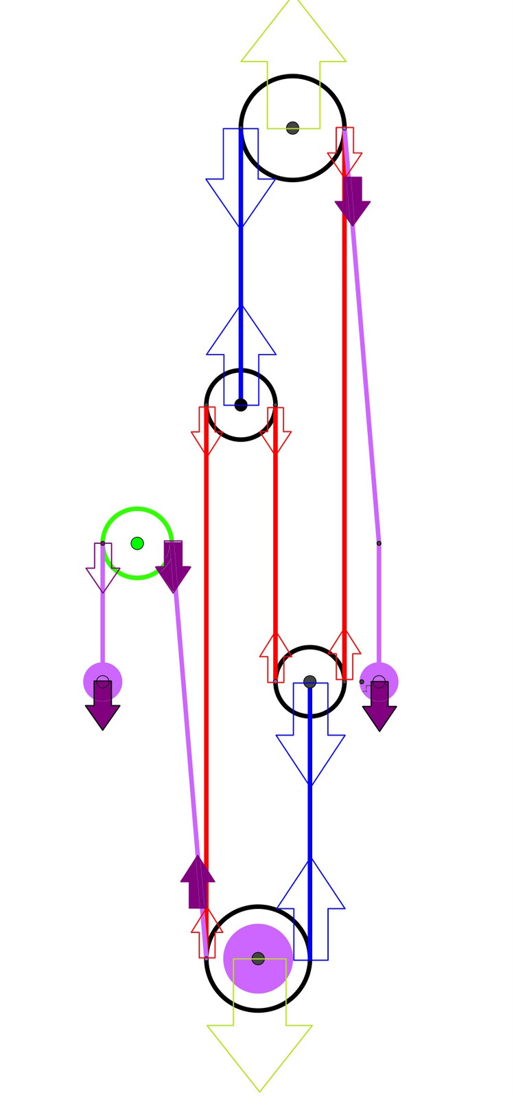
In order to transform it into a mechanism which is static, and so we can then study the mechanical advantage it offers when we put it in motion ( remember, we are talking about uniform motion, NOT acceleration ! ), we have to “add” forces. The interested reader will see the two forces F, indicated by the purple arrows, in the sketch of the Poldo tackle in equilibrium shown in a previous post.
THAT is knotsaver s omission / “mistake” : he examines the mechanical advantage of the mechanism, when it is in equilibrium, and he, correctly, finds it to be 4 : 1 - but the Poldo tackle itself, without the addition of the forces F ( or the existence of friction forces, which play the same role ), is NOT in equilicrium ! If we take into account the work consumed by the application of the forces F, or the additional work needed to overcome the equivalent friction forces, we see that the 4 : 1 mechanical advantage is reduced by half, and becomes 2 : 1.

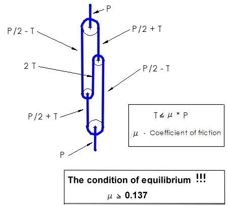
The second way is the “dynamic” way. One analyses the forces acting on each part of the mechanism, and he is assured that the ( “vector” ) sum of those forces, in each and every part of them, is zero. On each and every pulley, the forces are supposed to be counterbalanced, each of them cancels the effect of all the rest, so the pulley does not start moving to somewhere by itself ! :slight_smile:
Then, AFTER one has found all those forces, he should probably add some more, which would be missing, if the mechanism by itself is not static. In the case of the Poldo tackle, due to its simplicity and symmetry, it is very easy to do this - in more complex structures, it may become very difficult… The interested reader will see, at a glance, how the F forces counterbalance the rest. ( Note : In this sketch, I should had also shown, by long green arrows, the forces acting on the tackle by the load, on the axle of the one end-pulley, and by the anchor, on the axle of the other end-pulley - but I had not enough space to do this ! :slight_smile: The diagram was already very long, and those forces are 4 times as strong as the F forces, pointing outwards…)
After the addition of those “counterbalancing” F forces, the calculation of the mechanical advantage is a piece of cake : If those forces are, say, 2F ( as in this case ), and the load is 4L, the mechanical advantage is the ratio of the sum of forces acting on the lines of the tackle to raise the load, divided by the load to be lifted - that is , 4l / 2l = 2 : 1.
Of course, this is the “ideal” case : Actually, in “real” cases, there are always friction forces acting on the mechanism, so, when its expansion or contraction takes place under load, the forces we “feel” we have to apply, to lift the load, are not the one half, only, of it… However, we always calculate ideal mechanical advantages, because friction can not be taken into account so easily : it may depend on many things, it may be not-linear, it may depend on the speed the mechanism expands or contracts, it may vary during some phases of the change of the overall shape of the mechanism, etc.

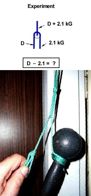
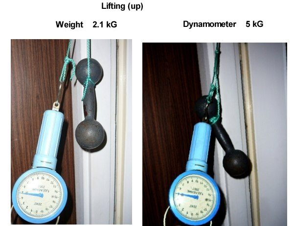
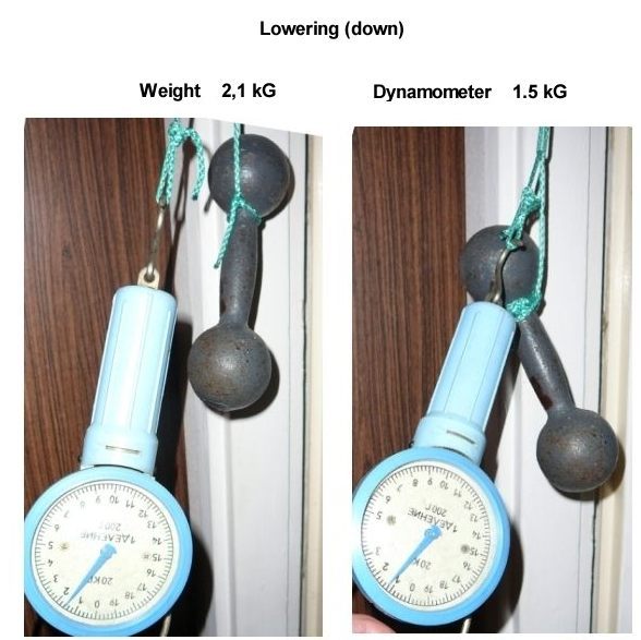
I have seen that knot tyers are not very happy, when they want/need to calculate mechanical advantages ! :slight_smile: :slight_smile: So it may be more interesting, and useful for us, to just TRY an actual “real” mechanism, using free-rotating, bearing-made pulleys, and slippery Dyneema fishing lines, and MEASURE the “real’ mechanical advantage by themselves. I am very interested to learn how much the 'real”, measured mechanical advantage of the Poldo tackle will differ from the “ideal”, 2 : 1 one…

Just in passing, I want to notice this : We can transform the original Poldo Tackle, into a “Stabilized Poldo tackle”, by adding two “counterbalancing” F loads, hanged by two more lines - and we will also need one more pulley to do this, because we should orient the second F force / load, too, towards the centre of the Earth ! :). Then, in order to calculate the mechanical advantage, we have just to measure how much the centre of mass of the TOTAL load will move ( the to-be-lifted load, plus the counterbalancing loads ) when a point P from which we drag a line of the tackle moves. The interested reader would only spend a few minutes to do this - but they would be his most worth-to-had-been-spent minutes in the study of the Poldo Tackle ! :slight_smile:

P.S. What can I do ? I had made a new quick and dirty sketch of the “Stabilized Poldo tackle” mentioned in this post. The green arrows represent forces two times the size of the forces represented by the blue arrows, and four times the forces represented by the red and purple arrows. One can easily see that the whole system, and each “free-floating” part / pulley of it, is in equilibrium. The tackle can contract and expand freely, under load, without the consumption of work ( provided there is no friction, of course ).
The to-be-lifted load and the “stabilising” loads are indicated by the purple circles. One can also see the green additional pulley, which can be hanged anywhere outside the tackle, and its only purpose is to re-orient the one purple line to the centre of the Earth :slight_smile: .


Stabilized Poldo Tackle.jpg

First of all, I want to thank both of you, Dan and Xarax, because I’m beginning to understand how Poldo tackle really works. I have been so fascinated by the self-locking feature (I consider it the best feature of the tackle!) that I have never studied it in detail.
I want to post another figure to complete the understanding of the moves (in the ideal-ideal case), so please look at the figure Poldo_moves_Pa-Pb.jpg.
If we apply force FB (in blue) on the left side (“good luck!”, as Dan said ;)) in this case we are able to move point PB by 2L in lenght whilst the load is lifted by 1L, so we have to double the force FA (in red and in brackets)
Note:

  1. point PA is lifted by 4L in length but now we apply a double force (!?)
  2. if we use both hands with the same force, the right hand will lift 2/3 of the load and the left only 1/3, for instance if the load is 30kg, F_righthand=F_lefthand = 5 kgf (kilogram-force ) ( a total of 10kgf) and so
  • if we use only ritgh hand we should have a 4:1 IMA …
  • if use both hands we should have a 3:1 IMA
  • if we use only left hand we should have a 2:1 IMA
    :-\ (a little confused!)
  1. with a blocked (fixed) C pulley we are analysing the “noeud a cremmailler”, I haven’t understood yet if it is equivalent to Poldo tackle
  2. we should consider the feature of lowering a load too
A little confused, indeed.  :) 
However, things are quite simple, provided you do not mess right and left hands, feet, ties, etc... :)  If you grab and pull the line which goes to the rim of the pulley, you have the 2 : 1 mechanical advantage. However, if you grab and pull the line which goes to the axle of the pulley, you have half of that - because, for a distance X a point on the line which turns around the pulley covers, a point on the line which "hangs" the pulley from its axle covers distance X / 2, so the mechanical advantage, from 2 : 1, becomes 1 : 1 - that is, it is evaporated !  :)  Moral of the story : Do not pull the pulleys themselves !

When you calculate the mechanical advantage, you are not concerned for the number of points from which you grab and pull the line(s) ! You are concerned only for the distance those points cover ( which is the same, of course, for all the points of the line ! ), in relation to the distance the centre of mass of the load covers at the same time. Your analysis is “kinematic”, do not mess the number of hands, amount of forces, and points of the line you grab with it ! Once the tackle is in equilibrium, it is either static or it moves with uniform velocity, which is the same thing. If your analysis is “dynamic” then you take account the amount of forces you apply - but we should not make a mixture of those two ways…
There are NO 3 : 1 or 4 : 1 mechanical advantages in the Poldo tackle ! The ( ideal ) mechanical advantage is 2 : 1.

( A humble advice : “See” the simple sketch with the “dynamic” analysis I had posted - you will understand the whole thing immediately ! I believe that you have not yet understood that you can not analyse the mechanical advantage of a system that it is not in equilibrium - and which, if it is left alone, it will start moving NOT with a uniform velocity, but with an accelerating one ! )

This “locking” is not achieved with any ingenious trick! :slight_smile: ! It is due to friction ( mainly in the end zig zag points ), which plays the role of the “counterbalancing” loads I had mentioned : they do not allow the line to slide from the one side to the other, although it tries… If you examine the distribution of forces, you will see that, without those counterbalancing loads and forces which stabilize the mechanism, at each end point, when the line “arrives” there, it is loaded by twice as much load as it has when it leaves from it - which would nt be possible, if there were no friction.

Hint - static friction :slight_smile:


Sily.jpg

Correct - but, in your simplification, you have distributed the static friction evenly, in all the four zig-zag points… I believe that the static friction at the two mid-tackle pulleys / tips of the eyes of the loops / mid-zig-zag points, is considerably smaller than at the two end-tackle points - the tensile forces running through the lines there are larger. So, in my simplification, I have placed completely self-balanced mid-tackle pulleys, and unbalanced end-tackle pulleys.
The role of counter-balancing those unevenly-loaded end-tackle pulleys, and the unevenly loaded lines passing from the two sides of them, is played by the static friction in those points - OR by the “counterbalancing loads”, denoted by the purple arrows.
I believe that, if one tries the Poldo Tackle with minimum friction = bearings in place of the end-tackle pulleys, he will see that the mechanism will not be “locked” by the static friction on the mid-tackle pulleys alone - but it will be locked, if he does the opposite. That will illustrate my point, that it is better to ignore static friction at the mid-tackle zig zag vertices, and concentrate our descriptive efforts in the static friction at the end-tackle zig zag vertices.

My calculation :

I do not understand your calculation… :-[ :-[
I see two end-tackle pulleys, the “higher” and the “lower”, which, when their axle is loaded with P, due to static friction, they do not rotate freely. Therefore, the tension of the incoming line is reduced by 2T - so the (P/2)+T incoming tension becomes (P/2)-T out-going tension : {(P/2)+T}-2T = P/2-T. So far so good… :slight_smile:
Now, we suppose that the two mid-tackle pulleys have the same size and are made from the same material, so the static friction on their axle will have “similar”, proportionally, effects. The problem is that the axles of those pulleys are loaded with a smaller load, the (P/2)+T. How much will the tension of the incoming lines in them be reduced ? If the tension of the incoming line is (P/2)-T, what should the tension of the out-going line become ?
To have the whole tackle in equilibrium, this (P/2)-T should become 2T, as you show in your first sketch.
However, this means that the tension on the out-going line will be reduced by b-3T[/b] : {(P/2)-T} - {(P/2)-3T}=2T

  1. When the axles of the (end-tackle) pulleys are loaded by P, and the tension of the incoming lines is (P/2)+T, we have a reduction in the tension of the out-going lines equal to 2T.
  2. When the axles of the (mid-tackle) pulleys are loaded by (P/2)+T, and the tension of the incoming lines is (P/2)-T, we have a reduction in the tension of the out-going lines equal to b-3T[/b].
    Am I missing some essential property of addition and subtraction here ? :slight_smile: :slight_smile: Where is the catch ?
    I do not understand the supposed “similarity” / proportionality of the 1 and the 2 ! :-[ :-[

( Mind you that we are talking about static friction, so the difference in the speed the pulleys are revolving plays no role ).

Take a simple test :slight_smile:

My Experiment.

Equipment:
Weight 2.1 kG + Dynamometer (kitchen scale)

Results:

For Lifting (up)

Weight 2.1 kG
Dynamometer 5 kG

Sum:
5 + 2.1 = 7.1 kG

Friction force:
T1 = 7.1 / 2 - 2.1 = 1.4 kG
T1 = 5 - 7.1 / 2 = 1.4 kG

For Lowering (down)

Weight 2.1 kG
Dynamometer 1.5 kG

Sum:
1.5 + 2.1 = 3.6 kG

Friction force:
T2 = 3.6 / 2 - 1.5 = 0.3 kG
T2 = 2.1 - 3.6 / 2 = 0.3 kG

P.S.
This is not a Coulomb friction but capstan equation.
https://en.wikipedia.org/wiki/Capstan_equation


1a.JPG

2a.JPG

3a.JPG

Why, in this “Stabilized Poldo tackle” , isn’t the IMA 4:1 ?
I’m missing the point…
(I’m studying the static friction)

The ingenius trick is the use of friction! :wink:

I am glad that you see you should calculate ( ideal ) mechanical advantages only in ( ideal ) stabilized systems / systems in With the “kinematic” way you use, you have to find out how much the load moves, when the point P moves, just as you did. However, in the “Stabilized Poldo tackle”, “the load” is NOT only the initial load any more ! It is the sum of the initial load equilibrium, where all the individual parts “do not move” = move with uniform, not accelerating speed, plus the “counterbalancing” loads, which play the same role as friction, and stabilize the mechanism. Therefore, you have to calculate how much the centre of mass of all loads is lifted - which changes your initial calculation. I had mentioned it in passing :

Static friction will not save you ! :slight_smile: :slight_smile: There is friction on the axles, between the parts made from rigid material(s) ( the axles and the disks of the pulleys ), and friction on the rims, between the parts made from rigid and the parts made from flexible material ( the pulleys and the segments off the rope )… Moreover, there is the perhaps not insignificant/negligible elongation of the parts made from the flexible material ( you do not use a chain ! :)), which you should also take account, because it changes the whole geometry - and the differences are not only between the lengths of the segments of the rope before the loading and after the loading, but also during the loading, during the expansion or contraction, because the lengths of the parallel segments, which are not equally tensioned, will not change proportionally to their lengths, and this will generate more friction on the rims, etc… In short, a “real” mess ! :slight_smile:
Why, on Earth, you need all that ? Just “see” my first sketch, with the “dynamic” calculation of the mechanical advantage of the original Poldo Tackle, where the ratio of the added forces F to the initial load is 1/4 + 1/4 = 1/2, so the mechanical advantage is a nice round 2 : 1. :slight_smile:

Struktor, I believe you are calling the cavalry !  :)  :)  You add more and more not-"ideal", "real" elements with friction ( the capstan equation... ), but in this way your whole description/explanation becomes less and less convincing ! 
You have [i]not[/i] explained on what exactly the difference between the tension of the incoming line and the tension of the out-going line you show in your sketch depends ! If it depends on both, the static friction between the axles of the pulleys, on the one hand, and the capstan effect, on the other, as you say now, you have to [i]calculate[/i] them ! I want to see why in the one case the difference is [b]2T[/b], and in the other it is [b]P/2-3T[/b] - for starters ( because, as an analysis of a "real" system, you have only [i]started[/i] to take into account the possibly [i]dozens[/i] of parameters which may alter the whole picture...), I do not need to now the exact value of T ! 

And, of course, I am not convinced in the hand-weaving arguments, “decorated” by those “experiments” ! :slight_smile: :slight_smile: Make a decent, as “ideal” as you can, Poldo Tackle, and measure the static friction on the axles of the pulleys in the two cases ( the more loaded end-tackle pulleys, and the less loaded mid-tackle pulleys ), which prevent them from rotating freely, and the capstan effect, also in the two cases ( when the incoming tension is P/2 -T, and when the incoming tension is P/2 +T ). We want to describe the mechanical advantage if an “ideal”, stabilized Poldo tackle - we already KNOW that it is stable :), we do not know why it is stable !

P.S. Moreover, sorry, but I do not buy this “capstan effect” thing ! The line goes through the tip of the eye, where it is squeezed by three sides, with different forces : the stiffness of the rope, the amount of “flattening” of the cross sections of the two segments in the area of their contact, even the length of the eyelegs of the loop, and the size of the eyeknot itself ( because the two legs may not be parallel : a line passes much more freely from a wider tip, especially if the rope is stiff …) are additional factors which aare not taken into account, and which do not have any relation with the calculations of the capstan effect !

I believe that the title, alone, of this post, should had been enough ! :slight_smile: ( We will never understand why we had not understood the whole thing this way right from the very first minute - but, from my personal experience with knots, that is happening too often, so I guess we should better learn to live with it ! :slight_smile: )
The double line / retraced Poldo tackle is made from one unknotted closed line : no ends - and no need for any end-of-line loops. It is one loop by itself ! :slight_smile:
Obviously, when it is maximally extended, it has 4 parallel segments, and when it is maximally contracted, it has 6 parallel segments. Therefore, if the ropelength of the line is, say, 24L, the length of the tackle goes from 6L to 4L ( so that 4 parallel segments x 6L each = 6 parallel segments x 4L each = 24L ). ( To calculate the mechanical advantage, we should also specify which line(s) we grab. and to which direction we pull it/them ).
Now, I like to imagine that THIS was the original Poldo tackle ! :slight_smile: :slight_smile: Poldo was just playing with a multi-folded closed loop between the fingers of his two hands, and he saw that, this way, he could easily expand and contract it, without removing any sub-loop from any finger - the rest is history. Of course, the idea to use, in those parts of the tackle he could do this, one line instead of two, was clever, too - but I think it was more straightforward…The truly ingenious idea was the multi-folded single loop ( where the single line traces this “endless” zig zag path ), which expands and contracts this way.

X, S, & K,
thank you for your patient persistence.
The realization of the not-quite-stable state
of an untouched Poldo tackle shook me into
seeing that the simple re-direction pulley (IMA 1:1)
requires much more than the “F” X indicates for
PT stability, so there must be something there.

But it is complex, and we really should have some
simply got actual forces of the structure in use
–for, after all, actual use is the point of a practical knot
or knot structure, not colorful diagrams and equations!

I’ve found the article about various such structures
–the obvious pulley systems and some of the more
sophisticated ones (Spanish burton & versatackle)–
by Charles Warner, in km023:13-15 (1988-Spring).
He tested systems both in pure rope and with “krabs”
for sheaves --the former showing worse friction. He
used 11kg weight to be lifted, and measured the
force to raise the weight with a calibrated spring.

His important initial remark is worth echoing:

From time to time one sees in the knotting literature (including [i]Knotting Matters[/i]) note on rope tackles. I wonder if all the authors have ever desperately wanted to shift a heavy weight and only had a length of rope to help. Whenever I have had the experience, I have been most impressed by the enormous friction in all the systems I have used. This friction is due not only to one rope rubbing over the other, but also, and usually most importantly, the rapid transfer of the sharp 180-degree bend along the length of the rope.

For the Poldo tackle, he attaches his haul line
to pull downwards on the upper end of the “Z” part.
(Let’s call the length that runs through the internal
sheaves “the Z part”, in distinction from the rest of
the structure, which runs from end sheaves to the
“axel” --X’s term-- or sheave-body (not through but
to) of the internal sheaves. I.e., Warner loads just
one of the two points indicated by Xarax, to haul
downwards on the structure (as he does for all
of his tested structures --and, yes, which adds
one gratuitous-to-mech.advantage sheave of
friction ; but, yes, is going to be a common need
for lifting (but avoidable if one were just pulling
something horizontally, or hauling upwards/downwards)).

Warner’s results for the PT are the worst except for
the simple 1:1 redirection (in rope/krab measurements,
19/15kg vs 23/18kg to raise 11kg).

But one thing I cannot make sense of is Warner’s statement
that “Although stated to hold a weight without anchoring,
I did not find this in my conditions.” --I can only think that
there’s some misunderstanding of this statement or what
he did : for, surely, with the terrible MA tested, this would
be a structure that happily didn’t move at all, absent the
(considerable) effort needed to make it move!!

NOW, with the insights given above,
I have taken X’s (K’s (S’s)) indication to attach haul lines
for proper effect to the by-the-anchor-sheaves ends of
the “Z” part, pulling resp. up/downwards as indicated.
NB: one cannot simply pull X distance from the sheave
for each end-of-this-Z-part, as the top sheave is fixed
in position (the anchor) and the lower one moves
in raising the weight --if one moves the haul lines joined
together, the distance between bottom and the
attached-to-it line will be half that of the other.

With a 10# barbell weight, I found that 10#
attached to joined-together haul lines didn’t move
the weight (and this is my slippery structure that DOES
move, with weight alone, slowly expanding the reach)
Adding a 2.5# weight will raise the weight, slowly,
slightly (adding 5# got a quick movement to raise …).

NB : The re-directional sheave that I used for converting
the upwards pull to downwards --and going downwards,
it was joined to the other haul line so I would weight
a single part and move the two of them in unison–,
was an actual, wide-diameter cheap clothesline(?)
pulley --not high-grade yachting gear, but well
more efficient than a 'biner or another cut-off plastic
bottle neck (used in the system)!

(I would like to see results using substantial materials
–e.g, 8mm rope and decent pulleys, and 50-100# weight!?)


Consider : the Poldo tackle is presented without any
good indication of how to work/use it --i.p., where to
haul, how to haul. Other MA systems have an obvious
haul line (though their workings might be sophisticated!).
That’s part of the problem. It is also obvious from static
analysis, that the maximum possible movement is not
much --1/3 of the span.

And that’s something I’d like to hear Knotsaver explain,
for his using it. After all, that was part of the OP, that
this structure had proven useful to him (or that he so
believes !). And I surmise that his use of it is in
the worse condition --rope-through-rope-sheaves.

–dl*