Deflection=ForceLength/(AreaE). So for steel at 30000 psi of stress, E=29E+6 and a length of say 240 inches, that’s about a quarter inch of stretch. It’d likely be more for cables. I have no idea what kind of experiment the original poster has going, but it sounds interesting. I don’t know how practical it is.
Hi Awatchi, thanks for coming back and settling our inquisitiveness - what a sweet project - I hope you can ‘pull it off’…
Amsteel Blue is as strong as steel wire rope of the same diameter, yet roughly 20% of the weight. It consumes a tiny amount of energy to manufacture it in comparison to steel, and its crowning advantage - it doesn’t rust ! Is it your idea to use it to pre-stress concrete? If so, it seems we could have a genius visiting our board…
BUT, this rope does have some weakness that wire rope does not, and as far as fixing is concerned, its most important one is that in comparison to steel, it is easily compressible and deforms to rupture under point pressure. Take a sharp knife to Amsteel Blue and press, the edge will cleave straight through - take the same knife edge to steel rope - well, you see what I am getting at. This polymer is the opposite of concrete, it is massively strong in tension, but it is like jello in compression. In using the rope for your project, your main challenge is going to be converting the rope tension into compressive force on the end of the concrete, because as you wrap the rope around the anchor point, the inner surface of the rope goes into compression against the anchor and you have to keep this pressure well below the deformation point or you will ‘cut’ through your rope.
The ‘knot’ for you anchor point is easy and is well defined for the use of this material - it is the spliced eye. The safe working anchor radius is also well defined - but don’t be surprised if it turns out to be greater than the diameter of the hole in your concrete spar, you may well have to arrange for the anchor to be well outside the end of the beam. Also, the spliced section has roughly twice the cross sectional area of the rope, you will need to allow for this to pass into the core of the spar.
But now comes your second challenge - the tensioning point. The ‘knot’ is again going to have to be a spliced eye which will have to be passed down the core of the spar and be long enough to protrude the other end. BUT, Amsteel Blue will stretch by ca 1% when under just 30% rated loading, so you are going to have to put the eye over the tensioning anchor, jack it away from the end of the spar to load it, then fit some form of concrete spacer between the tension anchor and the end of the spar.
If you can afford to sacrifice a little Amsteel blue, then there is an innovative grip hitch going crazy in the camping world at the moment called the ‘Whoopie Sling’ - it is effectively a giant VT grip hitch made by passing the rope through a piece of braid - much like the splice making the terminal eye. By using a grip hitch such as this, you could have a means of pulling tension onto the rope from within the spar, until you drew the tensioning eye loop out of the spar, slide in the tensioning pin, then release the tensioning rope which unfortunately has to be sacrificed, because there is no way to retrieve it.
The final aspect of polymer ropes you must consider is creep. Although the long polymer molecules have been pre stretched to align them during manufacture, they can still undergo plastic deformation under load. I have no idea how significant this aspect of plastic string is, but if it happens to any significant degree, then the load set initially, will diminish over time - Oops.
Hope this helps, and have fun.
Derek
Just had a thought that might make tensioning easier.
Just like they ‘spin’ suspension bridge hawsers in place, strand by strand, so you could (with a little ingenuity) ‘spin’ your tensioning rope in-situ.
Take a much lighter Amsteel Blue rope and fix it with an eye splice loop to an anchor pin.
Now loosely pass the lighter rope ‘n’ times back and forth through the core around both the anchor points in turn, where ‘n’ is the tension multiplier you need to safely pre-stress the beam.
Then tension each turn to the desired load sequentially, temporarily locking each loaded line while you set up to load the next turn, until all the turns have been loaded.
Finally, for the last turn, fit a sliding grip hitch with a spliced eye over the rope (again the ‘Whoopie’ is ideal). Pre load the last turn and slide the Whoopie hitch down in place and fit the eye over the anchor. Then release the loading tension to allow the ‘Whoopie’ to retain the end under tension. You might have to over tension the last turn in order to allow for the tensioning up of the ‘Whoopie’
Derek
Is the rope going to be free inside the concrete element or molded into place?
If molded, how well will the concrete grip to the rope? If it won’t grip properly, I suspect the tension will be compromised if the ends, or at least knots, are damaged.
Intriguing project none the less
Since concrete does not resist traction, and it resists compression very well, you can prestress it so that it doesn’t suffer traction in any part of the beam, making it flex less and have less fissures. (I live in Brasil, and learn in Portugues, so i don’t know how to explain this very well in English, sorry)
You got that right.
However, you can stress the concrete after it hardens, which is the way i am planning to go.
I understood most of your idea, but i didn’t understand what you meant by “Then tension each turn to the desired load sequentially, temporarily locking each loaded line while you set up to load the next turn, until all the turns have been loaded.”
The rope will be free inside the concrete beam, i suspect that molding it will not help much since i doubt that the concrete will grip the rope well.
As for the ends, that’s why i’m here. If there is anyway to solve this problem, i believe that the guys here will have the answer.
OK awtchi, I will try to clarify by using a couple of examples.
When you put a new shoelace into a boot, you cannot just thread the lace, then pull on the ends to tighten it up, the first few eyes will tighten, but after that, the force just does not travel past the eyes all the way down the lace. This is due to the ‘capstan effect’ see http://notableknotindex.webs.com/friction.html. So, we can’t just thread a rope several times around the two end anchors, then haul on the end and expect all the turns to tighten up to the same tension (unless the anchor bars have ultra slick surfaces such as hard anodised Al). Every time the rope goes around an anchor, it looses force, so we have to tension every run in turn.
Let us presume, that the two anchor bars are sitting in recesses in the ends of the beam (to protect the tensioning rope from damage and abrasion.)
Take a length of rope that is long enough to pass through the beam the required number of times (n) to give you the necessary load multiplier. Start the rope with a spliced eye and slide this over one of the anchor bars. Then feed the rope down the channel in the beam, around the other anchor, then feed it back to the beginning, then around the anchor bar again alongside the spliced loop, then back down the channel, again and again ‘n’ times. At this stage it is fixed on to one anchor by the spliced loop, passes back and forth from end to end ‘n’ times around both anchor bars, and at the moment it is hanging loose - untensioned.
Now an explanation on tensioning. I was top-roping my climbing partner once when he hit a particularly difficult part of the climb and called to me to haul him up over the part that he was stuck on. I leaned forward, took out all the slack in the rope and then leaned back, hauling the rope up 6". But it wasn’t far enough, he needed me to haul him up 18" to the next hand hold. With 70kg hanging on a climbing rope, they go stiff as an iron bar,and only 1/2" thick, you can’t grip them sufficiently to haul that 70kg up. So what was I to do? I let him down to his previous hold, then I took a loop and tied a Prussic loop onto the climbing line, it is an adjustable friction hitch. I hauled him back up 6", then I slid the Prussic down the rope, put my hand through the loop which gave me a good grip on the rope and hauled him up another 6". I then took the slack out of the rope above the Prussic and locked it into my belay plate. I then slid the Prussic back down the rope and hauled him up another 6", and so on until he was climbing again.
You can utilise this technique of two tension points to tension the first length of rope passing through the beam. Tie on a Prussic connections (or better a VT hitch), and slide it into the channel beyond the anchor bar. Haul on the Prussic connection to tension the rope. Maintain that tension while you work on tensioning the next rope.
Go back to the starting side of the beam and find the rope that comes back from the now tensioned line. Slide a Prussic onto it and into the channel, beyond the anchor bar. Haul on it to the required tension. Maintain that tension while you work on the next length.
Go back to the exit end. The first Prussic is now doing nothing because the rope is tensioned both sides of it. Remove it from the rope (using the VT hitch makes removal much easier) and fix it around the rope now running from the line under tension at the eye end. Slide the hitch along the rope into the channel and haul on it to the required tension. Repeat this tensioning end to end just as you would tension a shoelace all the way up the lacing.
The final run of rope has to be treated differently, because this run has to be tied off. By now you should have found out how the Whoopie hitch works, it is simply a length of the rope braid, opened up and the other rope passed inside it, much like one snake swallows another. Then when the opened braid is tensioned, it shrinks onto the inner rope, gripping it like a Chinese Finger Trap. This is exactly the way the eye splices are made.
EDIT : see the termination tensioning in the next post.
And there you have it.
Here is another refinement.
Make up a jig of timber with two anchor pins the appropriate distance apart.
Slip an eye splice ove one pin, then run the rope around and around the pins the required number of times. Fit prussic loops to them.
We will now make the Whoopie hitch in situ - perhaps we had better start calling it the Garter Hitch as Whoopie is probably a Trade Marked name…
Take the end of the rope one last time around the end anchor pin, then fit the end of the rope into a hollow Fid. Bunch up a section of the Blue Amsteel long enough to give you the necessary bury length for a splice and pass the Fid into, through and out of the splice bury section - this is your Garter Hitch. Make the end long enough to exit the beam and enough to grip onto to make the final loading haul.
Fit a length of split plastic pipe over the assembly and slide it off the jig pins. This premade assembly is now ready to slide into the channel within the beam.
Slide the assembly into the beam, then fit an anchor pin through the eye and all the loops, finish sliding the assembly into the beam and locate the first pin into its slot. Where the assembly protrudes from the other end, slide in the other anchor pin and tighten up the ropes to clamp the second anchor pin into place. You will have to slacken off the Garter Hitch in order to have the Garter eye protrude sufficiently to fit the second pin.
Tension all the lengths then finally tension the Garter hitch end to lock the assembly in place.
A possible alternative would be to have a lubricated shim around the anchor pins so as to reduce friction and allow all the tensioning to be achieved just by hauling on the very end of the rope - job done…
Three things to watch out for - as mentioned before, you will need to establish the amount of relaxation the rope has under constant load. Second, what is the impact of temperature on tension and upon relaxation rate, and finally what is the long term impact of oxidation or other chemical degredation on the rope?
NB: You may need to facilitate access in order to retension the rope over time.
Edit : 19 March 07:20 GMT change name to Garter Hitch and make into a single rope component.
Derek I think I can follow what you are trying to do here but I do think that the chances of a prusik or any other friction hitch gripping Amsteel must be slim at best - as I understand it HMPE just doesn’t generate enough friction (a triple fisherman’s knot has been shown to slip under load in Dyneema).
Barry
Hi Barry,
Yes, I have to agree that the low self friction of HMPE is a real challenge to sustaining knots. However, Polyester to HMPE has a much better cf, giving us the chance of using polyester as the friction hitch components. Also, with friction hitches, we have the flexibility of increasing the turns and therefore the gripping capability of the hitch.
But if the worst comes to the worst, and awtchi cannot get enough tension through the prusik hitches, then he can always go to the ultimate route of adding locked Brummel spliced tensioning lines into the HMPE. These would be sacrificial in that they could not be removed after tensioning, but the cost would be trivial, and with appropriately buried tails, would give full rope strength to the tensioning line.
Derek
How about twisting?
Just the same way as you charge a rubber band motor.
This will cause an uneven stress through the rope, one set of strands, half of them, less tensioned than the other, although it may facilitate tensioning, if for example the anchor on one end is resting on an axial ball bearing, then rotated, maybe until the bearing collapses and locks from the compression load, otherwise locked by other means. Tension on the rope may be calculated from the torque and rope diameter.
HI Injanyezi,
That is an interesting ‘twist’ to the solution. And Amsteel has such a low elongation under load, a 5m length expands by only 5cm under 30% loading. A double line shrinks by one rope diameter per turn, so in 11mm Amsteel, you would only have to give it five turns to tension it to 30%. There would be ca 80 braid turns in a 5m length of Amsteel, so one group of fibres would be wound up to 85 turns, while the other six were ‘unwound’ to 75 turns. So one group of fibres would be loaded to ca 60% while the other group remained essentially unloaded.
I wonder how a rope would perform under conditions like this, with essentially a whole load of redundancy built in against failure? The rope would at first be stiff against load, yet as it failed, it would expand yet still retain the load…
Of course, in this application, the result would still lead to a failure of the concrete beam as the beam would only be prestressed so long as the cable did not elongate.
Derek
Looking at this challenge, considering the material to be used, I hate to state this, but I think knots are the wrong way to go, so far. ![]()
I would consider a spliced sling where one end could go around the metal anchor bar (of as large a radius as possible) and the other end of the sling around a opposing wedge device that incorporates similar radius at the contact to rope face location.
The low slope wedges can generate a great deal of force. I have used them to lift houses that have settled foundations.
Attached is a crude drawing of what I am offering for your consideration.
SS
I have to agree Scott,
But I would ask, what criteria would be taken into consideration in making the choice between spliced sling vs eyspliced braid?
I note that there are a huge array of uses for Amsteel Blue that use locked Brummel eyesplices. Do these have some advantage over spliced slings?
One aspect of solution which came up in the discussions was the protection of the tensioning medium from damage when the beam is being located. If the anchors sit on the end of the beam as you have depicted, then some sort of protective cap needs to be fitted. Alternatively, one end at least could be recessed into the end of the beam, but it might be difficult to engineer a system of recessing both ends that also allows the use of wedges. Any thoughts?
Derek
Hi Derek.
Actually I just thought that a spliced sling would only have one join whereas the other has two. Plus it is a double strength tendon.
Then there are splice-less slings and that would be even better. Round slings are generally of a continuous fiber wound around a sizing form and then outfitted with a braided sleeve to contain and protect the fibers. The fibers can then form to the load attachment needs and the shape of the item being hoisted.
Yes, the accessibility, both good and bad, to the tensioning method could be addressed by creative blockouts cast into the concrete forms, along with the thrust plates. Effectively making recesses where the ends and device will be located.
More for the engineers to figure out. ![]()
It just seems to me that knots aren’t the right tool for this job. There are so many factors, safety and longevity, not to mention cost, to be considered and rigorously tested before implementing.
They are already using carbon fiber tendons for these type of applications and use specifically engineered anchorages.
Re: OP. Knots have been shown to severely weaken this material (Dyneema likes straight line tension, it has creep and amazing slipperiness) and their trustworthiness (knots) are still pending further exploration. So, I believe there will have to be a marriage of sorts between the rope and mechanical fasteners. Such as wedge type and mortar/epoxy style.
This has been very educational and I am learning some very interesting things.
SS
Reverse Paradigm:
(Though small experience with amsteel/dyneema slip/low stretch, applying rope stuff i use to scenario):
Don’t put knots in highest tension parts, use leveraged angle sweat/swig to tighten line not inline pulls/jig compressions.
Pillars, slick for slide, but right enough amount of friction to quickly call up; and keep purchases taken from tensioned line length.
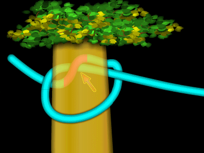
Finalize with tensionless hitch type strategy that doesn’t deform the loaded tension part with own rope part, perhaps even spiral around 1st turn around spar for many nip points w/minimal deforming main tension from pure inline, then just keeper/low tension eye around tension line w/minimal deformity.
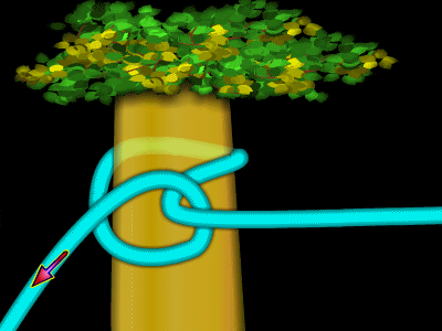
This is an adaptation of swig/sweat line, gives 2x1 leverage to bend tension line, by “Muenter”/backhand Turn(?) on spar.
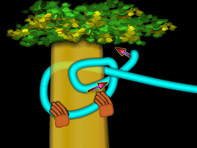
Made to work when was in tree, could only work end on spar, but this “Muenter” has a 2/1 built in to help the bending of the main line. Main line will wrap further around host spar, then need enough slip to slide back around spar, while not losing tension, and then bend main line again w/2:1 bend of “muenter” rinse/repeat ratcheting more line from tension /standing part to working end, can leg push off spar, impact etc.
Can convert to timber, cow, improved half etc. easily and back if careful for temp/perm lockoff.
Or hold nip to spar tightly as lacing working end thru, around back of spar, to pull nip deep around spar at convex point.
Finish with no/minimal deformation to loaded line with tensionless hitch, types of clove, constrictor/ground hitch etc.
Can get more nips to lock by main tension (for slippery use) by sliding bight of working end under where standing part hits tree, or poking bight thru near previous nip, would then spread nips so don’t bridge tension off of each other.