Hi Scott, I hope that you and yours are surviving this crazy lockdown.
As for feedback, I doubt that a child board on knot math will attract much attention. But, understanding the concepts behind knot functionality and exploring novel ways to quantify the parameters involved is certainly of interest to me at least, and clearly a few others that frequent here.
The OP was introducing us to a novel and delightfully simple way of determining cf for whatever cordage we are working with. The supporting math was, I believe, simply there to confirm the validity of the methodology.
As for cf being math, I think it is no more math than bringing breaking strain or pulley mechanical advantage into a discussion, but for those of us who study ‘what makes a knot tick’, cf is of far greater importance than the simplistic tests of loading to destruction - yet both revolve around using numbers.
While long ago I argued strongly for the dissolution of ‘Chit Chat’ into classifications that at least allowed us to focus on broad areas that we found particularly interesting, there is equally the opposite nonsense of subdividing our field into such minutiae that you finish up with virtually every post in its own child board. I appreciate that this is not what Mark is suggesting, but as we have seen virtually zero evidence of Knot Mathematics on this forum, I think the proposed new child board will remain desolate for some time to come.
Meantime, I would suggest that as there are so few numerically pertinent posts floating around, we all consider the mantra of -
My personal (and likely lone viewpoint) is that the IGKT is first and foremost a knot forum.
At its grass roots level, it is about knots and exploring aspects directly related to both existing and newly discovered knots.
The math is fine - but, it should be applied to a knot structure (rather than existing as an abstract concept).
It comes down to what the IGKT is purporting to be.
We’ve got visitors to this forum who do not speak English as a first language. We also have posters who don’t construct their sentences and paragraphs (ie their narrative) in a coherent and easily understandable way.
Anyhow, its a complex mix of people and competing interests.
I would like to think that it makes sense to apply the math to an image of a real knot - rather than existing as an abstract proposition. I’ve given examples of ideal candidates for this - eg… the #206 Crossing hitch is a candidate for applying the math directly to the image. And so is the ‘Tensionless hitch’ (#2047).
Full disclosure:
I am not a moderator. I am simply attempting to provide a viewpoint.
I believe in striving to be a good communicator - which means posting content that is coherent and easily understandable - even by the layperson. I also believe in supporting posted concepts with quality images that are real knots.
On the other hand, math can be it’s own border crossing shared language amongst it’s users.
A common language made millenniums ago.
It can decode what is going on, even internally where can not touch nor see.
i try to apply to modules as single item to focus on, then expand a group of those modules to a full blown knot.
.
The use of radians is more accurate, it actually took the stars ~365.25 nights to circle the Earth to circle, only rounded to 360.
That lends towards PI and more math.
.
Some of the math does actually blur by me sometimes not being formally trained where i wander;
but i never put that on the author.
My instincts once tuned in, have served me miraculously well; kept me alive and that includes knot insights where my math doesn’t go.
.
The site is about knots, i focus on working, load bearing knots. All load bearing structures are math.
Especially if want to decode what is going on in what stages.
Math is how we really pick stuff apart.
.
If show something per a knot and not abstractly, then mite stay ‘hooked’ to that knot.
Abstraction blurs by the stuff should not let eye stop at, to see the underlying commonalities in many.
Abstraction sometimes is like an X variable that can fit many things, without having to repeat the pattern 1000s of times for one lesson.
to then be pummeled and buried by lesson or raw memorize of see persisting pattern
finding pattern, is leveraged learning, covering points did not individually stop at.
Many things work like a computer game/program or even car.
many models, looks, by changing outer skin; but still the same mechanix ruling the item under that skin.
Math is a language of science, oft what we use to make something a science; perhaps knots nothing different.
.
On of the best things i ever did was figure out how to tell angles as shown in hash/second/minutes marks, and then immediately know sine/cosine and some tangents. Started with math, real work to figure, using at work as had to. But eventually became constant companion that was there on the fly immediately decoding accurately whatever looking at, immediately becoming more familiar how everything works in everything, to these understandings being second Nature. Became light play to use, even at work, feeling so good to accurately command and predict seamlessly with what was going on, and how it related to all else/where else could carry the lessons of that day to.
.
So yes, i give you math as others before, as the truest sharing; keys to all that. “Euclid’s Elements has been referred to as the most successful and influential textbook ever written.”
was/may still be the 2nd most printed editions of any book(wiki)
Just asking a question here…
(They say humans are doomed because we ask questions).
With regard to your post at reply #24; was there any particular knot that you had in mind to apply your excellent work to?
It would be great to see the math concepts applied directly to specific knots/hitches (particularly for readers who don’t have a strong math background).
And when I use the term ‘math concepts’ - it also includes math equations.
Or is your post intended only for a select group of individuals (just asking so its clear)?
Please, though just Muenter/BackHand Turn Base type shown specifically,
is there Crossed(on or off host) or Uncrossed Turn single or group of forming a Bend or Hitch where this would not apply?
.
i think this capstan and pulley effects are in ALL linear force fed (thru SPart of Hitch & Bend) controlling arcs of knot internals;
and also see same in ALL rigging; as concepts of rope mechanics engulfing ALL linear force rope usage,
of which Bends and Hitches are a small island/segment inside.
.
Once again, as defining contrast, separating Round Binding as a radial induced force
from host expansion evenly diffused all around w/o favored direction
from inside controlling arcs domain
vs. focused linear directional external force into controlling arcs of Hitches, Bends, Rigging etc.
Round Binding is all controlling arcs, evenly loaded until nip(s) w/o direction.
has no SPart for linear input during USAGE, perhaps a linear feed/SPart in setup, but not usage.
This is ingenious - BUT - in understanding the result, don’t you first have to quantify the cf for cord on cord and cord on stator?
Have you run this technique in real life, and if yes, have you observed any anomolies as load causes plastic deformation of the cord?
Also, you have given us a most ingenious method for studying the impact of knot structure on locking due to ‘cogging’ which is complex because the cord actually rotates as well as sliding.
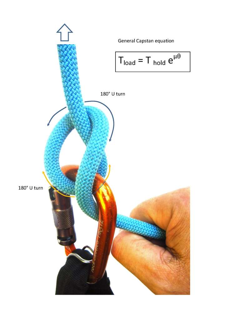
The #206 Crossing hitch (aka Italian hitch / Munter hitch) is a good knot structure to directly apply math.
The humble Italian/Munter hitch is used routinely around the world as a belay system (ie it is used to arrest falls).
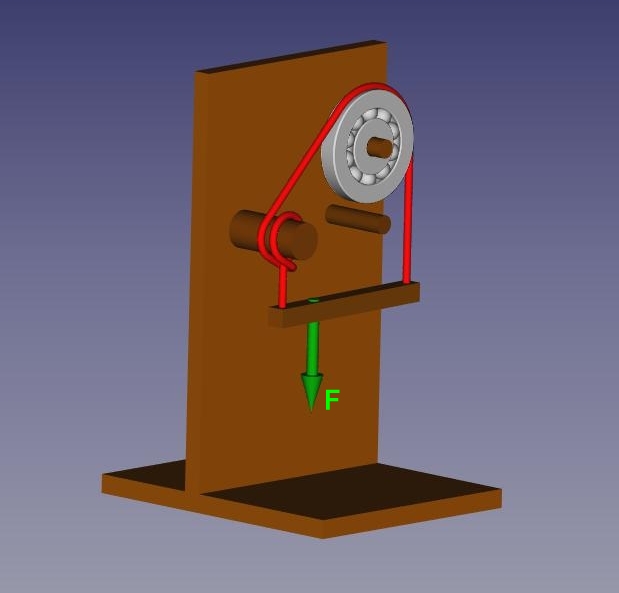
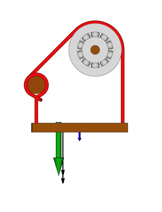
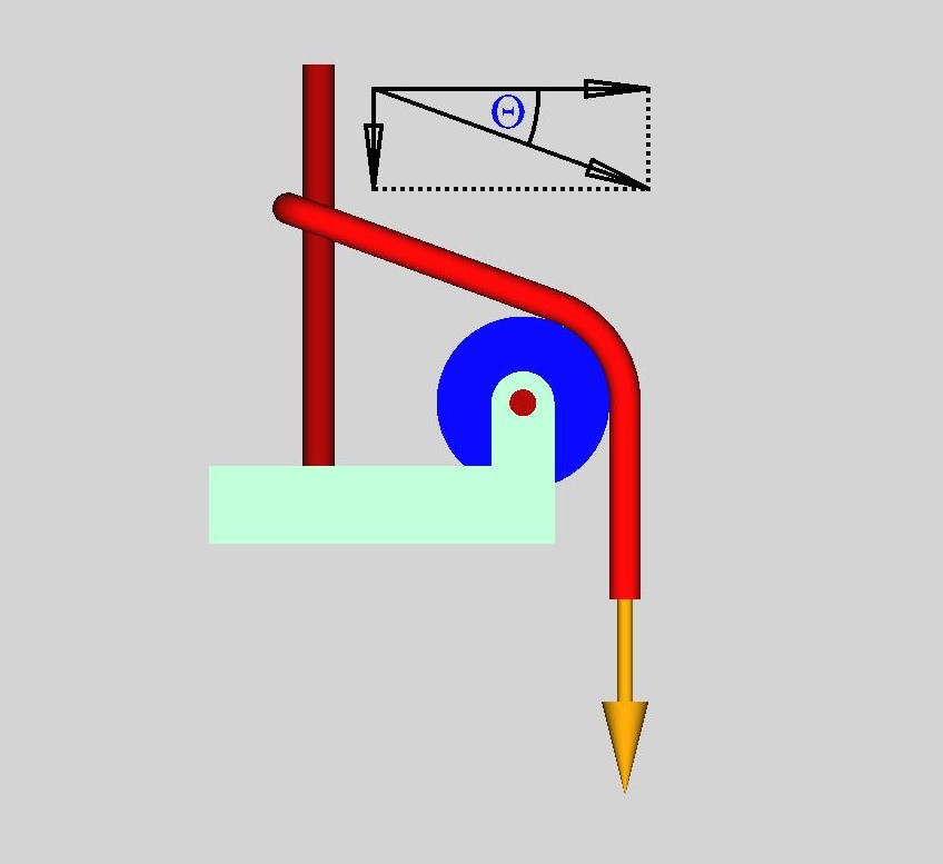
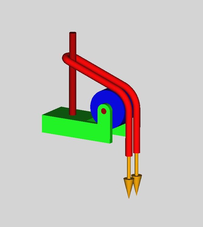
Refer to attached images.
Perhaps a keen mathematical wizard could apply the math directly to the images, with step-by-step calculations?
The top image is a proposed test rig to measure load at the tail (brake-hand) end of the climbing rope.
Changing the angle of the brake-hand with respect to the carabiner will affect the degree of grip strength required to arrest fall.
The pulley is not ideal - having approximately 5% loss of efficiency.
Could also substitute a carabiner with 5mm bending radius (which is realistic) but adds another variable.
I’m still waiting for my new linescale 3 load cell…at the moment I cant measure force.
Maybe a math wiz could make predictions - and then I’ll check with load cell later?
…
Math is good
And practical application to a real-world ‘knot’ is even better.
The contact angles in my real-world image of a #206 Munter hitch were (obviously) approximations.
I wasn’t really intending to say 179.134 degrees, or 189.3256 degrees (or whatever) etc.
The 180 degree U turns in my photo image are just approximations.
Be that as it may, is it within your scope of math knowledge to be able to directly apply the capstan equations directly to the Munter hitch photo image?
Or is this outside of your scope of knowledge? (its a genuine question - not an insult!).
I will have my new load cell late October, and could verify your calculations.
The coefficient of friction for rope-on-rope, and rope on metal is something you would have to work out?
Note also that under load, modern synthetic rope flatten a little bit and so there is more surface area contact (particularly at the rope on metal carabiner interface).
I suppose that if you knew the tension force at the load cell, you could work backwards and derive the coefficient of friction?
There will be static friction to initially overcome and then once the rope is moving, it is now kinetic friction?
I can easily measure the load while the system is in equilibrium.
Not sure how I would measure load at the brake end of the rope while it is moving? Maybe attach the load cell to the free end of the rope, hold it in my hand and then allow the rope to flow through the Munter hitch (and observe the LCD screen display)?
Summary:
What do you think ‘struktor’ - can you apply the math direct to the real world image of the Munter hitch and try to predict the force on the brake hand end of the rope?
Make your math predictions with calculations directly applied to the Munter hitch image (rather than abstractly on computer generated imagery).
Then I could check your predictions once I have my load cell…
Assumptions:
Rope would be EN892 Beal ‘Joker’ 9.1mm diameter Link: https://sport.beal-planet.com/en/mountain-line/1418-5132-joker-91mm-gd.html#/14-color-blue/58-length-50m
Carabiner has radius of 5.0mm
Contact angle (rope-on-rope): Approx 180 degrees / Pi radians)
Contact angle (rope-on-carabiner ‘first’ point): Approx 180 degrees / Pi/2 radians) - feel free to be more precise!
Contact angle (rope-on-carabiner ‘second’ point): Approx 90 degrees (variable)
Mass held by Munter hitch belay = 100kg
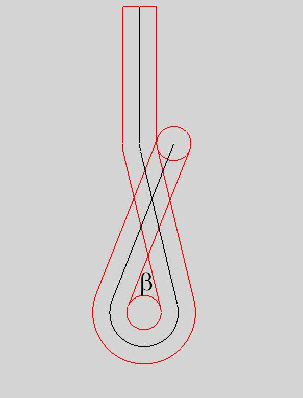
I use a large simplification.
How does rope-to-rope friction work?
They can be simplified by adding an insert?
The figure shows a rope friction insert.
Nice eye candy, what are you drawing with please Struktor?
i L-earn from drawing too, is all geometry..
And note that drawing tools basics are always a flat linear face or radial for 2D objects;
as these are important concept differences all across the board into drawing as knotting etc.
Thanks so much for links too!
.
In reply #30 tho, i do look at only the 180 arc opposing the pull from opposite side of the host as the only radial friction component that uses all tensions for seating to host to give then controlling frictions, nips and grips(w/oppsing180). Using both the byproduct of deformation as side force and the force holding primary against Load too, as 1 for seating forces to host.
But i shy from calling The SPart (that for me ends halfway around the circle where 180 starts) and the pull from Bitter End seize as radial friction but rather more linear parts especially viewable here where 1 end pull towards Load if each of these legs. But in in any case more linear rope part if endpoints in opposing directions. Pure axis inline not a harsh point for there is no cross axis resistance, so directional claiming just a directional axis (vertical vs horizontal etc.) not a big point as would be in rigids that do resist on the cross axis.
.
Uniqueness of 180 arc would be that both ends, as center apex does, as in fact the whole component does
pull and work all as 1 in the same unique direction, as no other form does.
giving structural arcs to bridges and ropes etc. thru this geometry.
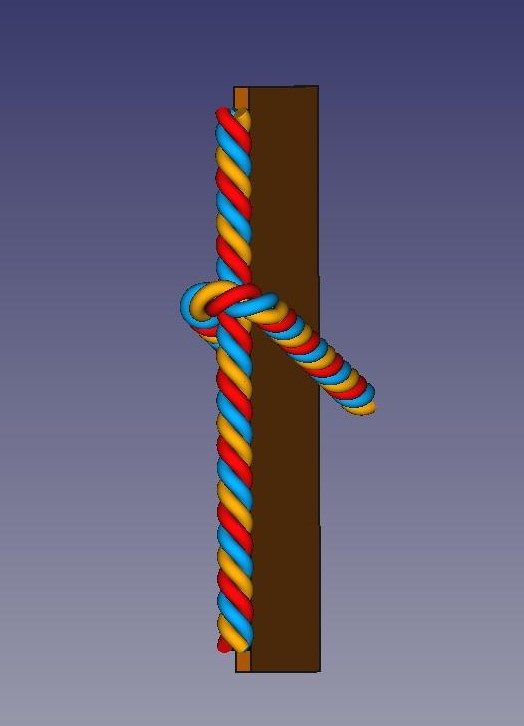
The rope slides down the vertical rod.
It will stop before it reaches a right angle.
This is due to the angle of friction.
The same will happen when the rod is replaced with a rope.
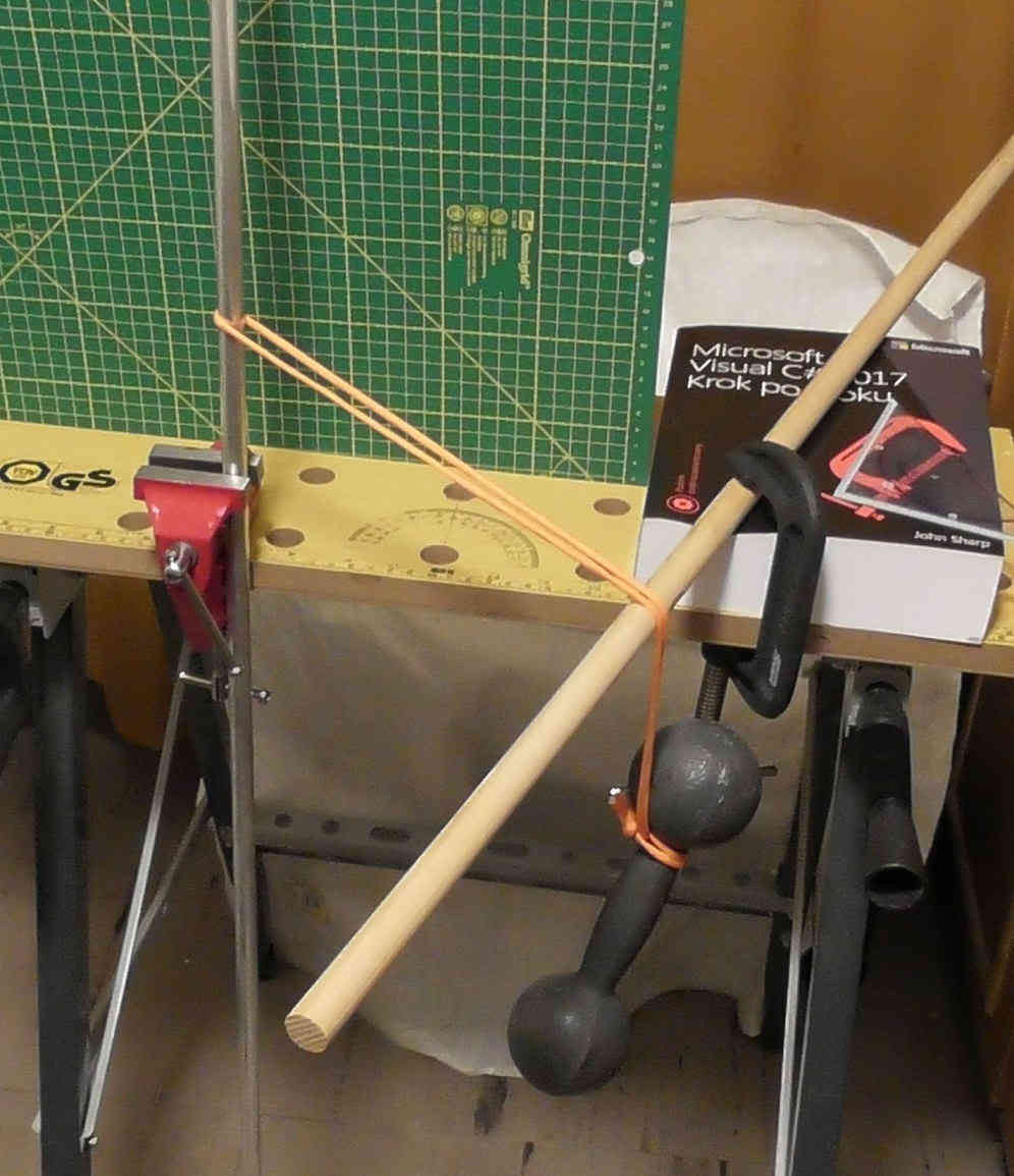
Hi, I have just tried this form of cf test rig with a slight variation, Instead of a vertical rod I clamped an 11mm DMM aluminium bena horizontally. I passed a length of 550 nylon paracord around the flat end and took this horizontally to a load. The cord had 180 degree surface contact.
I then moved the load end horizontally until it just started to slide and marked the angle. I then moved the load in the other direction until again it just started to slide in the other direction, and again marked the angle. The angle was reasonably constant with various loads with a total swing of 26mm at a distance of 100mm from the contact point on the bina - or += 13mm from the perpendicular This made the tan of the angle to be 0.13, i.e. 7.4 degrees.
Now the web reference you gave stated tan θ = μs , or 0.13 where previously using the capstan test system I had arrived at a μs value for 550 on polished aluminium to be ca 0.09, so sort of closeish…
BUT - although the cord load made little difference to the slip angle, the ark of contact certainly did. Of course, this is directly in line with knots such as the prusik , the VT where multiple turns rapidly escalate the grip.
So, do you have any idea how we are supposed to incorporate the number of radians of contact into the sliding angle method?
Part of it tries to determine the static friction coefficient of a 3 mm polyester cord on a bamboo spar (turns out to be some 0.15 +/- 0.03, see Table 2 and the graph before it).
The method uses the same Capstan model but employs regression analysis to find the most likely/plausible value of the friction coefficient for this pair of materials based on a range of contact angles (wraps), a range of working loads, and the measured rope tension reductions resulting from those arrangements.
One useful consequence of doing it this way is that it allows for estimating the realistic uncertainty of the computed friction coefficient value, which turned out to be relatively low in this experiment (given the simplicity of the equipment and procedure used).
I think that using similar techniques to estimate friction of rope-on-rope within knots will be problematic - there are papers describing such attempts in the textile industry. It’s complicated…
Figure 2 in the same paper above shows the general results for a Munter-type construct as well. It turns out in this setup that adding a Munter hitch was worth about one extra round turn (360 deg) on the spar in friction terms.
It is possible to roughly estimate the friction coefficient of rope-on-rope within the turn in Munter construct using the data in the paper (by splitting the friction into three parts: rope on spar prior to Munter turn, the Munter turn, and rope on spar following the Munter turn). For the cord used in the experiment, it seems to be somewhere in the 0.40 - 0.45 range, which is, not surprisingly, about 3 times higher than the coefficient of friction between the same cord and the bamboo spar surface.
Measuring (or guessing) the friction coefficients between a particular rope and a carabiner and rope-on-rope can probably lead to a fair estimation of the tension reduction in a simple Munter on carabiner (including the effects of angle changes of the free/holding rope end - to increase or reduce the friction) but the model will likely fall apart when applied to more complex knots.