Measurement of the coefficient of friction for the capstan equation.

We sometimes doubt whether we have assumed the correct value of the friction coefficient.
However, there is a simple method to verify its value experimentally.

The measurement method is shown in the figure 1.
It consists in changing the position of the weight (force) F on the board.
We note the minimum value of the a/b ratio for which the board tilts.
For this value (a/b) min , we calculate or read the coefficient of friction from the graph (figure 4).

Tl :
Tension in the Loaded End of the Rope
Th :
Tension in the Held End of the Rope
μ :
Coefficient of Friction for the Rope/Cylinder Interface
φ=3*π :
Total Angle Swept By All Turns of the Rope in Contact with the Cylinder (in radians)

Derivation of the formula to calculate the friction coefficient.

We measure the minimum value of the a/b ratio for which the board tilts.

A lever in balance
Tl/Th = a/b

Capstan equation
Tl/Th = e3π)

From a comparison of equations
a/b = e3π)

After transformation
ln(a/b) = μ3π

Formula for the coefficient of friction
μ = ln(a/b) /(3*π)

The images shows an improvised measuring apparatus.
Measures the friction coefficient of a pine roller and paracord 550.

The last stable position of the board (image 2).
a/b = 28/2 = 14
μ = ln(a/b) /(3π) = ln(14) /(3π)= 0.280012679

The tilt of the board appeared (image 3).
a/b = 28.5/1.5 = 19
μ = ln(a/b)/(3π) = ln(19)/(3π) = 0.312414679

Estimate:
0.28 < μ < 0.31


image3_unstable.JPG

Pretty slick and simple , thanx!
.
My pivotal understanding to this roots in a paper that seems to have disappeared again

but find in the wayback machine @ web.archive.org
.
http://i made a spreadcheat beginning with the flat mated surface co-efficient standard like from Berkley National, MIT, engineering toolbox etc.
then on next page different numerical increments of RADIAL co-efficients, related noted rope/host in the scale of numbers
(just flats of mated materials x PI to take from 1 side linear to 4 sides - corners= 3.141592.. type strategy)
per 180arc on host
1pi Radian /180 is a focus for me here also to staying on vertical or horizontal axis with center compounding point of arc
Capstan theory would not apply to Binding against swell i’d say
all individual rope points equal tension to nips in Binding vs degrading force thru arcs to ballast/ nip w/capstan effect
no compounding point, for all points equal pressure against equal round expansion..
i think this as from radial induced, diffused, directionless force source (vs. focused direction of linear input)
So capstan theory needs linear induced force to controlling arcs by that model
degrading force thru rope from end to end, from input to output >>to final ballast
BUT, applies/expresses that degrading tension thru to end, against host by radial position from source, focused linear input.
thus 2/1 point in pulley lesson is in same direction as input pull
the linear direction(al) axis seems maintained
the compounding point of arc >>is commonly greatest force of arc
the device/host of how those degrading frictions are applied against host to peak

@ struktor

Nicely done, especially the use of two pine rollers to give you a larger lever! ( since those 30 cm O.D. pine rollers are hard to find, lift, etc. )

This arrangement appears to give you odd multiples of
https://igkt.net/sm/index.php?action=dlattach;topic=6928.0;attach=26531;image
for the swept angle. Expanding on your idea, adding a third pine roller exactly between the two you already have with the paracord threaded below it would seem to give you the even multiples of
https://igkt.net/sm/index.php?action=dlattach;topic=6928.0;attach=26531;image
.

Edit: Correction - the contact points of the third roller would have to be placed at an angle of
https://igkt.net/sm/index.php?action=dlattach;topic=6928.0;attach=26531;image
/4 (45 degrees) below the contact points of the other rollers.

Thank you.

Formula for the coefficient of friction
μ = ln(a/b) / φ

Figure 5 shows the measurement for the 2π angle.

For φ = 2π
μ = ln(a/b) / (2*π)

Hey Structor, lovely exercise - thanks for bringing it to us.

I guess this is the static coefficient of friction. Do you have any thoughts on a method for determining the significantly lower kinetic / dynamic coefficient?

Also, wrt understanding the stability of a knot, do you have any thoughts on how to determine the cf for cord against itself?

I like your method of improving sensitivity from 3π to 2π. Presumably by simply removing the round turn on the rhs spar in the original configuration, we could further reduce the factor to just 1π.

I would be particularly interested in a method to actually quantify the magnitude of ‘cogging’ in knots where the flow of cordage within the knot is either supportive (+ve cogging) or destructive (binding or -ve cogging). Again, do you have any thoughts on how this might be approached?

Derek

Fasten the rope pieces to the cylinder surface (fig. Cf_rope_rope).

Presumably by simply removing the round turn on the rhs spar in the original configuration, we could further reduce the factor to just 1π.

I would be particularly interested in a method to actually quantify the magnitude of ‘cogging’ in knots where the flow of cordage within the knot is either supportive (+ve cogging) or destructive (binding or -ve cogging). Again, do you have any thoughts on how this might be approached?

Derek

This complicates the construction of the device.
The cylinders must be turning.
You must also add the lock to the board with scale.

μk: kinetic coefficient of friction
Formula for the coefficient of friction
μk = ln(ak/bk) / π

The rope must be sliding.
We give a/b > ak/bk

The cylinders must be turned slowly.
We want to lift up a heavier end.
It will be successful when a/b <= ak/bk.
When a/b > ak/bk it will stay down.
To check it, we shift the weight and unlock the board.

Hello and thank you struktor for your good work.
Everything I am writing herein is intended in good faith.

In your opening post in this topic thread…

We sometimes doubt whether we have assumed the correct value of the friction coefficient.
May I enquire which knot or hitch is this statement intended to apply to?

I am surmising that perhaps it doesn’t apply to a ‘knot’; which is a self supporting structure that doesn’t require a ‘host’.

I am thinking maybe #2047 Tensionless hitch?… in that the equations appears to be dependent on the existence of a host object (where rope material turns around)?
It is also possible that your statement might be intended for some type of slide and grip hitch? Although a slide and grip hitch (when loaded), tends to crush its host - so there are compression forces also acting. That is, it isn’t the case that grip is solely determined by the number of turns but, compression forces also play a role.

If this is an exercise in pure math with no particular application to a specific category of knot species - I am left wondering if the forum moderators might contemplate adding a new category to the IGKT forum?

If the moderators are willing, perhaps a new category could be added - and titled; “Mathematical concepts and explorations”.

EDIT NOTE:
Found this video from Richard Delaney regarding a #1763 Prusik hitch pull test.
Link: https://youtu.be/CaX4g5wgZnU

Hi Mark, I would like to thank you for your opening assertion and would like to echo your sentiment myself. In a field where we all hold strong perceptions and opinions, it is all too easy to give and take offence where none is intended, especially where those opinions and perceptions are in conflict.

Having said that, my comments that follow will be in contradiction to the views you have posted and I would like to assure you that they are meant in an educational / discusional context and certainly not with any intention of offence.

I am surmising that perhaps it doesn't apply to a 'knot'; which is a self supporting structure that doesn't require a 'host'.

snip

It is also possible that your statement might be intended for some type of slide and grip hitch? Although a slide and grip hitch (when loaded), tends to crush its host - so there are compression forces also acting. That is, it isn’t the case that grip is solely determined by the number of turns but, compression forces also play a role.

While the application of an understanding of cF and its use in hitches is obvious, it would be completely erroneous to surmise that it did not pertain equally, albeit with greater complexity, to knots that do not contain a ‘static’ component. Your observation that grip hitches rely on the creation of ‘crushing’ forces in order to function, suggests that you do not realise that these forces derive from the ‘Normal’ forces imposed on contained cordage by the number of turns imposed upon it by that component of the knot.

Within a knot, whenever a loaded cord changes its direction around another cordage component of that knot, it sheds its tension into a ‘Normal’ (i.e. perpendicular) force against the underlying cordage compent. The whole of the functionality of the knot depends totally on the generation of frictional and compressive forces through the turns and geometry of the knot. As you will have seen with cordage with exceptionally low cF, many normally viable knots simply cease to be viable because thier construction has not created the opportunity for the internal ‘capstan effect’ to sufficiently amplify compression and subsequent frictional loading to stabilise the knot.

Understanding cF and the capstan effect upon the function of all knots is key to understanding the functional construction of knots.

Derek

Hello Derek,

You likely (and probably) entirely missed the underlying purpose of my post.

This topic thread contains no apparent knot species for which the mathematical content is directed.
That is, it appears to be framed as pure math.

There is a wide readership - and not all who visit the IGKT forum have a solid grasp of math.

The grass roots of this forum is knots and knot tying, rather than pure math.

So some readers may be left wondering how the pure math applies to a knot - since no specific practical examples are tendered. And because no specific practical examples of knots were tendered, it is left to the imagination of readers to link the math to some imagined knot structure.

You might also have missed that I have asked the forum moderators to consider adding a new child folder titled, “Mathematical concepts and explorations”.

As for the principal thrust and underlying purpose of your post - which is to point out shortcomings in understanding of the ‘normal force’ - I can comment as follows:

In a nutshell, the ‘normal force’ is the force that surfaces exert to prevent solid objects from passing through each other and it is a contact force that acts perpendicular to the surface that an object contacts.

I did not specifically include the word ‘crushing’ the surface in that definition (although in this instance, crushing is likened to strangulation rather like a python snake wrapping around and crushing its prey). Also, consider that the host typically undergoes plastic deformation when being crushed (rather than elastic deformation) - sort of like boots sinking into the mud.

Now, you may wish to debate this as a serious omission and point out severe gaps and weaknesses in my understanding of knots - I am happy for you to publicly point out such deficiencies :slight_smile:

In terms of crushing its ‘host’, a slide and grip progression hitch may contain ‘n’ number of turns (which wrap around the host).
Force per unit area is well enough understood - in that the crushing of the host may not necessarily occur in a localized point position - but may be distributed over a distance. Depending on the exact geometry of ‘a’ slide and grip hitch, force may be distributed or it may be localized on its host.

Again, the fundamental issue is that I do think the discussion of pure math without a specific reference to a knot structure is moving away from the grass roots of this forum. On the other hand, if images of knot structures (eg such as slide and grip hitches, tensionless hitch and #206 Munter/Crossing hitch) with mathematical examples might have more practical appeal.

Now - if you wish to declare that I am a lone voice, or lonely in pointing out these matters, again, I am happy for you to do so :slight_smile:

Apart from that, hope 2021 is shaping up well for you!

EDIT NOTE:
While I was contemplating my suggested deficient understanding of knots and the normal force (and possible lone voice), an image of a #206 Crossing hitch suddenly popped into my consciousness.
Images of the capstan effect and coefficients of friction danced around in my mind…and I yearned for a mathematical proof for how brake power manifests from the geometry of the Munter hitch (when used as an improvised climbing belay).

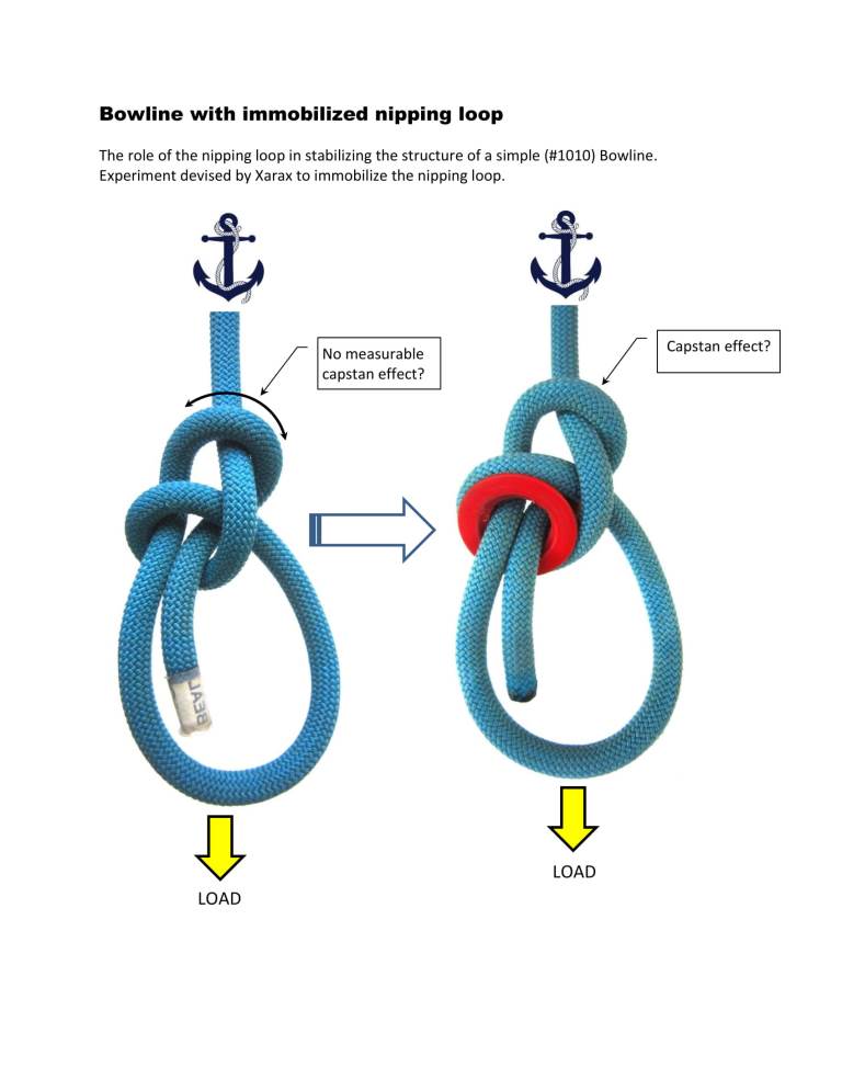
I’ve also added an immobilized simple (#1010) Bowline originally devised by Xarax.
This was in relation to a potential capstan effect created by the collar against the SPart.
I don’t believe a mathematical analysis of the role friction played - and a capstan effect - was ever definitely undertaken. I do recall a fair bit of shouting and the odd insult or two for good measure…but might be worth another look.


Bowline with immobilized nipping loop.jpg

i go with the capstan equation in the att_frict paper (mia still so using webarchive wayback machine)
.
It has a very logically built formula, to this target. In fact shares some similarities to Euler’s(pronounced Oilers) Identity, called the most beautiful formula in math etc. (eccentric crowd). Euler was one of the greatest mathematicians ever, popularized PI symbol from math club to worldwide use and much other math notations. Schooled under the Bernoulli ‘math dynasty’, and carried on from them.
.
Euler’s number is logarithm of 1, logarithms added together multiply numbers on sliderule well enough to put man on moon and bring back whole.
Euler’s number (e) is used in calculation compounding interest, population growth, disease, rust growth etc.
So is basis here for compounding friction radially, similar elsewhere linearly but by distance.
Then take the accepted table of cF for2 linear mated materials and multiply by PI to get a ‘Radial cF’ conversion (my translation of his work).
Take then ‘e’ and raise it to the power of how many 180 arcs x Radial cF.
.
winCalc or other in scientific mode:
On page_6 he gives his rule of thumb .25 for (nylon)rope on aluminum

this is a standard linear friction cF , convert to radial cF i say by multiply by PI = 0.785398.. as ‘Radial cF’
(Mr. Attway paper shows formula of all 3 elements, for table i created compound element of Radial cF’ logic)
on most scientific key boards have ‘e’ for Euler’s number and x^y (x to the power of y)keys and ‘(’, ‘)’ keys
tap ‘e’, ‘x^y’,‘(’ paste saved Radial cF ‘*’ then number of180 arcs , then tap ‘)’ then ‘=’
should give matching numbers to his page_7 showing 3,5,7 arcs for leveraged multipliers of 10,50,250 of control leg over load leg
(more accurate if calc and save PI x .25 and use whole string)
i get some variance on 7arcs with what he states, but then carries well to the rappel rack and fig8 next 2 pages.
e to the power of the reusable Radial cF (saved copy to paste) x number of 180 arcs
.
i hope that is clear logical explanation of what is used and why
and once have the ‘Radial cF’ just multiply by arc count (180=arc), and use as a power of compounding element ‘e’
as minimal math knowledge to reachable target
.
His analysis is very root to my own, including watching the amount of 180 arcs, fan belt examples, usage of PI etc.
but i only find in linear input to controlling arcs
and directional effect from same as like pulley, as a reciprocal opposing end of arc force range in all rope arcs, including inside knots
But only if linear force input, not Round Binding radial force input to same arcs,
then no linear to radial conversion, so no capstan effect nor no retained linear direction for pulley effect
So all points in Round Binding against radial ‘glow’ swell are equal until nips, not receding tension of capstan nor compounding force of pulley
My capstan etc. spreadcheat (link)
.
Crushing forces inward from linear input to me would be a pulley effect of competing compounding arcs.
2 opposing pulleys with rope around both, has 2 x 180 arc contacts, just as single capstan does(as Truckers w/pulleys also)
crushing inward as if 2 pulleys pulling together towards center
This is all connected, and math is the language of tracking and comparison to give definition.

With regard to:

  • relevance, it would seem that a fair amount of leeway would be afforded to those posting on a board whose title includes “Concepts and Exploration”.
  • the OP being general, not about a particular knot structure, and left to the imagination of readers - kudos.
  • the use of Math, a picture is also worth a thousand words, what posts and boards should we restrict them to?

Where any particular discussion will take us is difficult to guess.

Pure math related discussions are great and open new lines of thinking.
The ‘concepts and explorations’ actually has the word ‘Knotting’ in front of it.

I think the moderators are contemplating adding a child folder titled: “Mathematical concepts and explorations”
I would support the creation of such a new topic folder.

I would suggest that any pure math topics should be linked to a practical knot - with illustrations to assist readers to follow the concepts posted.

All of this boils down to what the IGKT forum purports to be.
Is it a math forum or is it a knotting forum?
If both, ideally there should be a way link to the two topics into a practical application.

The Guild is a forum on knotting. And so, we?ll keep it as such.
Any mathematical concepts presented here should be knot related and applicable to the use of knots/rope.
Understanding the forces that knots use or will see can be eye opening to the understanding and perhaps better utilization. That is what the ?Knotting Concepts and Explorations? Board is for.
That said, posts of pure knot theory or math don?t truly apply. Very many of the members have little interest in the formulas, unless they can actually apply them.

So, unless I get a huge amount of feedback to the contrary, I?ll not add a child board for ?Mathematical Concepts and Explorations? at this time.

Please keep the discussions knot related.

SS369

The 180 arc, in the capstan formula, is a defining cross verification of my focus and theory .
The count of 180 arcs in this ruling science is used with the 2 constants i gave to minimize the math as hopefully not too much.
The now mia att_frict simply opened many doors for me .
.
A Capstan with full 360 Round mounted only, has as many 180 arcs as a Trucker’s Hitch Geometry.
Capstan Effect/math is one extreme use of arc(s) in linear force to arc control rope mechanics.
Pulley Effect/math is the opposite/reciprocal extreme of linear force to arc control rope mechanics.

Reciprocally at extremes where as get more of one at the loss of the other
Knot mechanics, inside of rope mechanics, are ruled by arcs that are either more capstan friction or pulley directional effect
But only if linear fed.
As have tried to show these things and how pivotal in many ways; have to try to prove with math at some point
and it can show a continuous more tangible fabric of understanding, rather than isolated points.
It is a language, but not everyone’s, just my take from other side of aisle.

Hello KC,

Can you provide an analysis of the #206 Crossing hitch (when used as a belay system for climbing)?

Please refer to my image posted at reply #8.

The ‘Munter hitch’ - is definitely a knot structure that fits within the general concept of the IGKT.

No one has really provided a proof of how the Munter hitch works.
That is, by altering the trajectory (pathway) of the free end of the rope - it is possible to vary the brake power.

Questions:

  1. Does the Munter hitch employ a ‘capstan effect’? (yes / no)
  2. If yes, how does the capstan equation apply to the Munter hitch?
  3. Why does varying the trajectory/pathway of the free end of the rope alter the brake power?

Can you please provide a simple and concise explanation? (with diagrams to illustrate concepts - so a layperson can understand the concepts)…

Also, if possible, can you also look at the simple (#1010) Bowline and comment on whether a capstan effect plays any role (yes or no) at the collar? If yes, can you explain the capstan effect in simple terms (with supporting math) so a layperson can understand it?

I hope this fits within the broader purpose of the IGKT?
That is, math with worked examples applying to a real practical knot :slight_smile:

I for one am very interested in an explanation of how the Munter hitch (#206) works…

As always, i specifically find the capstan effect and it’s reciprocal pulley effect in ALL linear force fed into 180 arc(s).

the 2 effects are opposite extremes of arc powers, increase in capstan effect is a decrease in pulley effect etc.
The off host crossing provides friction but more pass thru than Crossed on host, and doesn’t self cross as Round Turn belay may.
The Muenter SPart is stable self centering flow not seen in the other 2 basic compound Turn forms.
On a carabiner or hook can get even more effect than if flatter across like spar, w/o sides furthermore being pressed/molded around SPart more so than in flat region .
.
Forms mentioned to me are of the BackHand Turn genesis, to include
Half-Hitch as not quite, Timber as extended but single bearing.
.
How could a Muenter not work?
it is as an incomplete Round Turn, not 3 arcs unless fold back towards input around host.
But it does have Turn on host and turn around SPart as more frictions and control of SPart more by biting into it.
i think stronger w/ Round Turn around SPart so is pulled more along than across SPart.
But with single turn style on tree have used Muenter as a Swig to tighten it’s SPart across it
then slide foundation of knot around too far the other way and draw swig again.
.
Muenter controls by friction as any other. Round Turn is uncrossed with 3 arcs, Clove base/Crossed Turn is 3 arcs + ON HOST cross
Backhand Turn types have 1 arc on host, and 1 crossing off host
to me not as complete to the others until a 3rd arc around host bring Bitter End back beside input SPart, like Cow with last leg not reeved thru.
ABoK points out a few times that BackHand Turn gives a double bearing, BUT only requires 1 pass.
Of course Muenter is 1 leg thru base form of BackHand Turn, while Cow is dual leg thru, 1 leg bearing.
Girth is 2 leg bearing. Typical choker sling/Bale hitch is 2 leg bearing, but self adjusting.
.
Capstan effect answer in any 180 arc(s) build, includes Bowline collar, but to very minimal extent.
for the collar is not very loaded to press the issue/empower the effect
most hold comes from Half Hitch, especially on rawest side going into collar, then yes some reduction to less around arc collar.
but not much, as there is not much powering it to induce the effect.
.
i hope i have already explained how linear fed force to arc control, is a conversion w/loss
linear can only use part of tensions for friction and then compounds by distance.
arc can use all of tensions, cosine and sine for friction BIG game change, then compounds by DEGREE
Arc can finesse cosine and sine together as one to MUCH greater force control, than linear.
host mounts should be round /arc NOT square/rectangle etc of linear faces

Munter hitch (#206)

Does such a substitute scheme make sense?
Equivalent diagram fig.1
Equivalent diagram for equations.fig.2 fig.3

Sample results:
μr=μ=0.1
α=β=57.1⁰
T1/T4=2.5


2.jpg

For the Munter hitch, starting at the loaded end of the rope, the tension in the rope decreases each time the rope curves. For the sake of clarity, let me mention what is obvious; the rope curves at those points it is in contact with another surface and also obvious, the tension is constant for the straight sections of the rope. The amount of decrease in the tension at each of these points of contact is given by the Capstan equation using the coefficient of friction between the two surfaces in contact and the angle of contact.

The above explanation is something of a simplification in that the first curve from the loaded end of the rope is at a collar which due to the extent of its wrapping produces “internal normal forces” which would need to be taken into account for a complete analysis. In Physics, this is known as the “Stacked Blocks” problem.

Independent of the above simplification which ignores these internal forces, however, a rigorous comparison of the braking in the Munter hitch can be determined. Using agent_smith’s image of the hitch as reference, define “TLower” as the tension in the free end of the rope in the Munter hitch when the free end is in the “Lower” position. Raising the free end into the “Upper” position essentially produces an additional curve and contact in the rope which, due to the Capstan effect, will produce an additional reduction in the tension of the rope in the Upper position, “TUpper”.

Using the Capstan equation,

TLower = TUpper * e μφ or

TUpper / TLower = e -μφ

where we have defined:

[tr]
[td]μ :[/td]
[td]Coefficient of Friction for the Rope/Carabiner Interface[/td]
[/tr]
[tr]
[td]φ :[/td]
[td]Additional Angle Swept By the Rope in Contact with the Carabiner (in radians)[/td]
[/tr]

For example, lets say that the additional curve for the Upper position wraps an additional angle on the Carabiner of about 90 degrees, that is,
https://igkt.net/sm/index.php?action=dlattach;topic=6928.0;attach=26531;image
/2 radians, and the coefficient of friction is 0.1. The tension required to support the same load in the Upper position is only 85% that of the Lower position. Conversely, but in this case, approximately (due to the internal forces), if the tension in the free end of the hitch is maintained as one raises the free end, the load that could be supported in the Upper position would be 117% of that supported in the Lower position. If the hitch was just able to slip at the Lower position, raising it to the Upper position should stop the slipping.

Nice work DDK.
Finally a post that communicates ideas and concepts in a more coherent and understandable way.

All thats needed now is to apply your math directly to the image I have attached.

Please consider that not all visitors to the IGKT forum are math geniuses. Being able to clearly communicate complex ideas so that the layperson (or non scientific) public can easily comprehend is the hallmark of genius.

Anyhow, the next step is to apply the math directly to the image - so the layperson can comprehend it.
I hereby attach an image of the #206 Crossing hitch for that purpose… (#206 is more widely known as the Munter hitch to rock climbers).

To me, especially as less math has been called for;
i simply count the 180 arcs on the mated surfaces as the att_frict research paper states..
1x against host and another time against SPart
.
My standard rule of thumb is 3 arcs for lowering, as like Round Turn, or same crossing self to Crossed Turn.
Here we have only 2 in Munter until fold back around host to be kinda Cow with only 1 leg thru off host crossing and other out,

but input and output are now laying next to each other.
But, 3arcs is probably my log reference and reduced that to 2 arc Munter that slides easier.
.
The other quantity here i see, another fave.
The self centering aspect of Munter lent to the SPart by the surrounding rope parts.

As it gets tensioned, these parts are more rigid and form would be rope guides as like we carved into the round host slightly to maintain positioning. i see this ‘beauty’ in Constrictor and Bag etc. as well.
A Round Turn can cross self in powering and seize, Crossed Turn base is already crossed, but decidedly control side crossing over load side..
Munter/Backhand bases can’t cross self to seize hard like the Round Turn and Crossed Turn bases when only 1 leg thru off host crossing.
i do recognize some more friction for the just not bottom side, but also these sides crushing increasing rope contact area in like what happens in ring or hook host with double bearing.