Measuring cf and applying an analysis to the Munter

This topic intends to offer a simplified method of cf measurement and will then attempt an analysis and breakdown of the Munter hitch as requested by Agent Smith.

Lowering Weight method for cf measurement.

Considerations:-

The method is based on the Capstan formulae and suffers the limitations this formulae faces when it meets the ‘real world’. Despite these limitations the method offers a rapid, simple and inexpensive means of determining cf for cordage on typical belay materials and a means of extrapolating this to simple cord vs cord systems.

Materials and equipment

A Luggage scale
This does not have to be highly accurate (all measurements are going to be comparative) but it should be reasonably linear.

Reference weights to measure linearity : I happen to have a 2kg and a 1kg Instron reference weights, but so long as you have two weights the same (roughly 1kg) you will be able to check your scale linearity at 0kg, 1kg and 2kg.

A Carabiner I used a DMM belay bina - ideally it should have a flat belay section to keep the coils from riding up the sides.

A Stand to hang the bina and scales (coathook on the back of a door is ideal)

Cordage I used 550 nylon Para-cord

A Notepad to record results

A Calculator that has the ln function (Natural log)and the pi constant.

Setup

Suspend the bina on the test stand so that it hangs ca 1m from the floor
Suspend the scales above the bina so that the attachment point is ca 20cm above the bina

Calibrate

Turn on the scale and check that they read zero
Hang the ca 1kg weight on the scale and record the result
repeat with the 2kg weight and record
hang both the two and the one kg weight on the scale and record the weight..

Check that the results are linear progressions i.e. multiples of x1, x2 and x3. If the results are not linear by more than ca 20g, send the meter back to Amazon. Today. most cheap load cells are amazingly accurate.

cf Measurement

Tie a 1m length of 550 Paracord to the scale load point and tie the 2kg weight to the bottom of the cord.
Record the scale readout this will be the 0 turn value or Load input

Now make a single turn about the bina spar. lift the weight and support the weight just below the scale.
Lower the weight so that the coils tighten on the spar but the weight is still held up from reaching the scale.
Check that the scale reads zero.
Gently lower the weight so that the scale starts to take the weight. The cord will gently flow around the bina until the scale takes the weight. Allow the weight to gently settle and for the slow creapage of load to stabilise. The weight now displayed is the load out after one turn of cordage has stolen a proportion by friction.
Record the weight for 1 turn.

Lift the weight again and make a second turn around the bina. Again, while supporting the cord below the scale, allow the weight to settle onto the coils on the bina. Make sure the coils do not overlap.. Now again, gently allow the load to slip the turns by gently lowering the weight onto the scale. Again, wait for the the creep to settle and record the scale value for 2 turns.

Repeat this process for 3 and 4 turns.

Now do it all again and see how good your reproducibility is. you should aim to eliminate variations until your results do not vary by more than ca 60g

Now for the calculator magic.
enter the T0 value and divide it by the T1 value. This is the ratio of Lin to Lout.
Now press ln - this will give you the natural log of of the ratio.
Now divide this by pi and then by 2 (this is because there are 2 pi radians in a single full turn.
The result is the static coefficient of friction for your cord against your bina.
Record the result.

Clear the calculator and start again by diving T0 by the T2 value.
proceed as before ln, then divide by pi, but now because the test had 2 turns, there are 4 pi radians, so divide by 4.
Record the result of cf for a 2 turn capstan.

You should see where this is going, repeat for the 3T and 4T results but divide by 6 and 8 respectively.

The results should all be relatively similar. My trials turned out to be between 0.082 and 0.09 but there were a few cranky results that turned out to be due to me letting the cords catch on the shelving or not letting the results settle.

Give it a try and share your results.

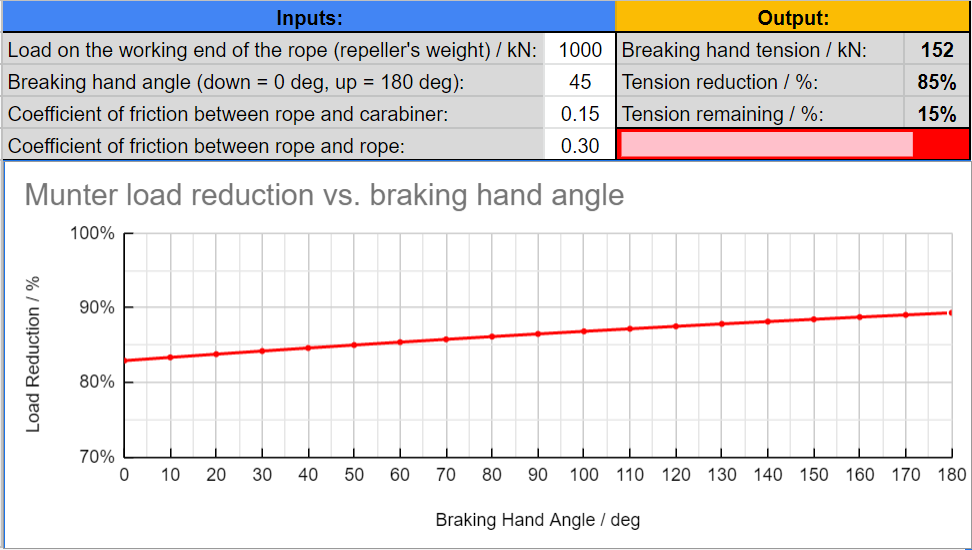
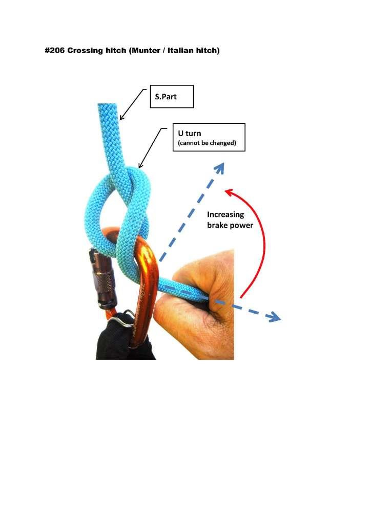
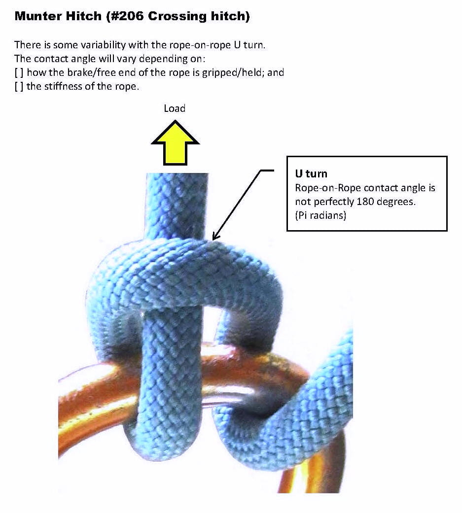
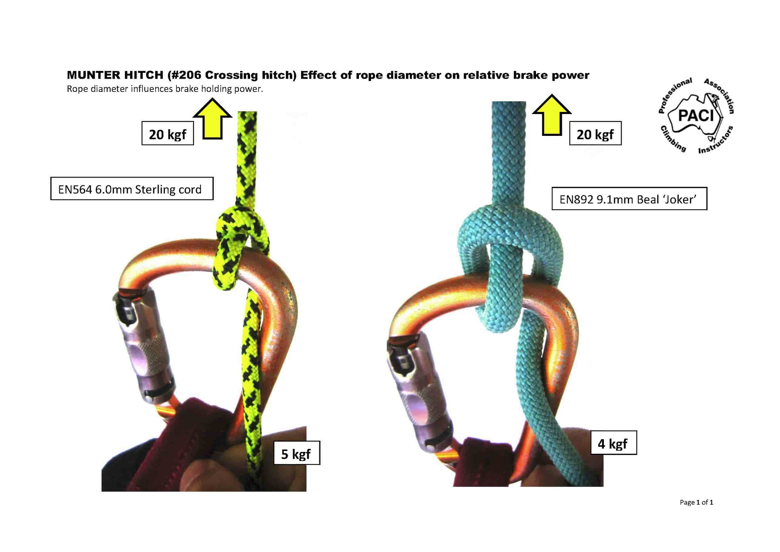
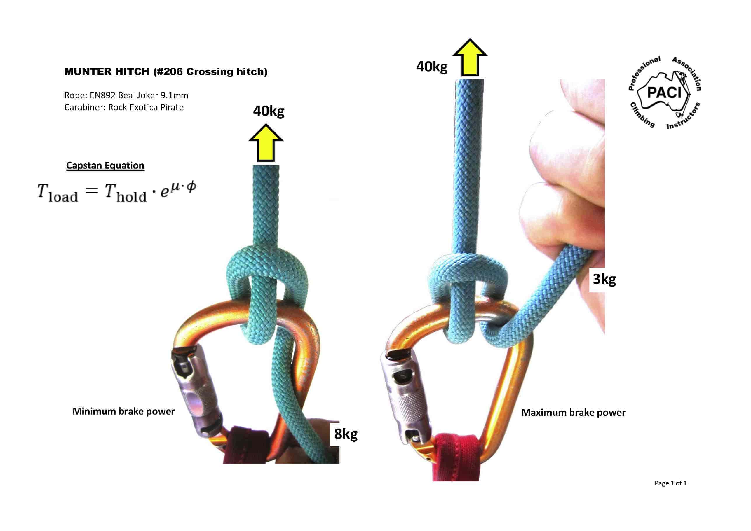
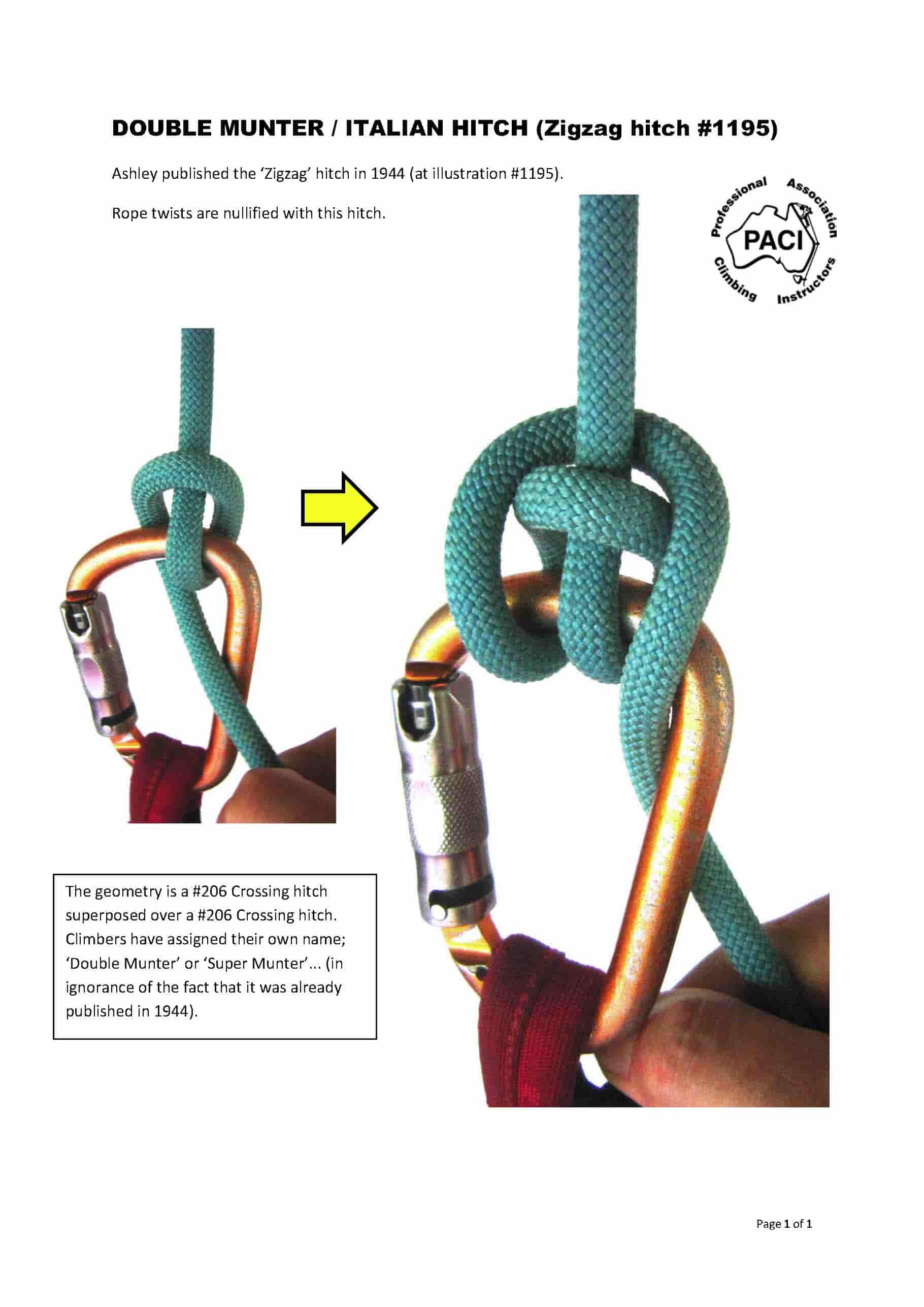
Next I will post an analysis of the values for the Munter

Derek

You may want to take a look at Richard Delaney’s method of measuring the coefficient of friction (this paper, pp.: 83-88). His method is a little more elaborate than both yours above and what I’ve done (which is similar to what you’re doing, but uses a set of masses and regression rather than averaging) - likely leading to slightly better estimates of the kinetic friction coefficient. On p. 88 there is a list of FC’s for a different combination of materials that he has obtained.

If there is a realistic estimate of the rope-on-rope friction, you could try this calculator to estimate/predict tension reduction by the Munter on a carabiner. Be aware that in this calculator, which divides the Munter into a series of three friction sections along the rope entangled in it, the contact angles are ‘baked-in’ the way I thought was realistic for the rope-carabiner system (but they can be unbaked if you have a better idea).

If the rope-on-rope friction coefficient is unknown, one can back calculate it if there is a set of tension measurements on the Munter - if you assume that rope-on-metal FC is accurate and applicable and that the contact angles between rope and carabiner and rope and rope used in the calculator are about right. I estimated the rope-on-rope friction for a 3 mm polyester cord using this method to be some 0.4 as explained in this thread.

OK, time for some results:

First the linearity calibration

Reference wt Display value
Nothing 0 g
1kg ref 980 g
2kg ref 1980 g

Given that these cheap scales have a resolution of 20g, this is a very acceptable linearity.

First test using 550 Paracord on 11mm Bina with 1kg weight

Number of round turns holding weight calculated cf
none 980 -
1 T 520 0.101
2 T 280 0.099
3 T 160 0.096
4 T 80 0.099

Second test 550 with 2kg weight
Number of round turns holding weight calculated cf
none 1980 -
1 T 1020 0.106
2 T 620 0.092
3 T 360 0.090
4 T 200 0.091

The cf values were a lot lower than my expectation of 0.3 to 0.4 for nylon against Al but were consisten enough to work with (I am begining to wonder if my 550 is really nylon !!)

550 Munter with 1kg
holding weight ln(load/holding)
200 1.589
160 1.812
180 1.695
--------
Average 180 1.699

550 Munter with 2kg
holding weight
380 1.651
420 1.551
400 1.599
--------
Average 400 1.587

Don’t worry about those ln(load/holding) values, I will cover them in the next post.

i think pulleys compound force potential, while this capstan effect compounds loss from that potential in pulley systems; at some point overtaking the pulley system increase.
.
i have more, but will wait.

Indeed KC, pulleys and friction are the beating heart of our knots. Only by gaining an understanding of the role of these components can we aspire to gaining an understanding of these cord machines.

The common perception of a pulley is of a freely rotating means of diverting the flow of cord with as little frictional resistance as possible. These have been at the heart of our great ‘Force Amplifiers’.But I would argue that static pulleys play a significantly greater part in our use and operation of our ‘Cord Machines’. In contrast to the rotating pulleys, a static pulley frictionally restricts the movement of a cord while enabling its direction and the force it carries to a designated point within the knot. These pulleys are principally load amplifying components within the knot.

This load amplification ability has two modes, namely ‘Feed Forward’ and ‘Feedback’ . In the cases of the capstan and the Munter hitch, ‘Feed Forward’ is employed. A small anchor force is applied to the anchor end, the static pulleys then direct the cord around the pulley surface, creating a ‘Normal’ force and through the cf, amplifying the small anchor force. This increased force is fed into the next section of cord which in turn amplifies it further and again passes the increasing force further into the coil Sufficient turns are employed to amplify the small anchor force to a level able to resist the intended load forces.

That is ‘Feed Forward’ amplification, but should the loaded SP be brought into contact with and across the anchor end, then it is capable of generating large ‘Normal’ forces and very high frictional effects. This immediately elevates the anchor force, which is amplified through the coils giving a massive frictional resistance at the SP loaded end. The loaded end can never escape this clamping, as any increase in SP force is always amplified to something well in excess of the feedback force. We deliberately utilise this facility to ‘Lock Off’ a knot. In the Munter for example, by passing the SP over the anchor end, the hitch becomes jammed.

The Munter can be release from its jam by taking the SP load away from the anchor end, but this effect of ‘Feedback’ lies at the heart of Jamming knots. In these knots, when load is applied, the structure of the knot is such that feedback amplification is fed to the area of the WE but is in turn locked by another loaded part of the knot. Constrictor and Strangle knots have the structure that once loaded the amplified compression cannot be let off and the knot remains jammed solid.

One interesting thing about this progressive amplification is that it is not linear. For example if a coil is able to amplify its anchor load by say a factor of 3, then a 1kg anchor load feeds a the next loop with an anchor load of three kg.. This loop then amplifies its load by x3 and passes on a new load of 9kg, the next one 27kg… The first loop increase the load by an additional 2kg, the next loop by 6kg, the next by 18kg. We can predict that the next would add on a further 54kg…it is an exponential amplification and that is why we need the magic of e to be able to predict what the various bits are doing.

Next post, lets take to pieces the figures we measured for the Munter.

Derek

NB - of course, all this discussion / explanation is completely wrong - you cannot generate or amplify a force simply by wrapping a cord around a pulley. The reality is that the force applied by the SP load is progressively lost by friction to the static pulley - I just find it easier to envision the force of the anchor being amplified rather than the force of the load being lost == same math, just easier to see in my ageing ‘mind’s eye’

i see as same;
for me pulley and capstan are extreme outer benchmark examples of all arcs, that are the secret or ropework.
Loaded Knot parts, etc. in arc fall between these outer extremes factors of the powerband available to play with; and gets some of each characteristic from each parent extreme on this wide spectrum.
But they are as like ‘antagonistic reciprocals’ to each other along that shared line, where by gain of 1 dictates the loss of the other, then combined to the whole. Much as cos/sine as opposing poles of the powerband, wave etc.; have to give up one to gain of other etc.
.
Only these things, can show as if open microscope to the same elemental functions hidden within the knot microcosm.

But of the same materials, forces, angles and laws etc.
Must make distinction of WORKiNG/loaded, force bearing to apply theories we seek.
Also, Strangle, Constrictor, Groundline and fave Bag FAMILY/class , self locking descendant of the self-crossing Clove
are excellent examples of it is not the name, but USAGE of Radial Binding (radial force init against and from inside radial arc control w/o friction loss) vs. if SPart ‘fed’ of force init as linear from outside knot micorcosm powering same Constrictor now is conversion from linear to arc control at the capstan losses from the conversion, that Binding doesn’t have.
But the loss is found in Hitches and Bends of Linear force init thru SPart(s).
Type of force & DIRECTION, and if converted at trade off loss are organically pivotal factors;
that can ninja by if don’t train to focus to them purposefully.
.
With cos benchmark as linear force direction, no cross axis resistance so DIRECTIONAL AXIS alignment i think, not necessarily what geometry shows as STRICT ALIGNMENT of RIGIDS that do have cross axis resistance by extreme contrast.
.
To me simplest 2/1 pulley setup with imperfect legs/not parallel, gives cos+cos math; at losses from 2xPotential by deflection from apex direction as a simpler, arithmetic, scalar linear progression
But sweat/swig perpendicular at Achille’s Heel of cos=0 of Samson angle across is a cos loss, but at more of a multiplying type math(than previous additive) to extrude force.
BUT, capstan math more as a cos+sine expressed in EXPONENTIAL math.
i guess these are more of my ‘pivotal ninjas’ that so unassumingly can sneak by the eye as so common in plain sight.
.
In modelling the Muenter, Backhand Turn forces would think would keep and eye on aspects given as in reverse of Dan (the man)Lehman’s Tumble Hitch.
.
As like Pulley theories must accommodate also Parbuckle as even sometimes better than pulley dragging load, and friction byproduct turned from foe to friend as traction. Better pulley affect without pulley, sling etc.!

I made a few changes to the Munter on a carabiner model the way I see it. I think it may be sufficient to predict how the Munter will reduce the rope tension if the 2 coefficients of friction can be reasonably estimated for a particular setup, which I figured was the objective. Whether it represents the reality sufficiently well needs to be verified.

p.s. Derek, is this model any close to what you want to accomplish?

Munter on a carabiner model/calculator


Screenshot 2022-11-23 154108.png

Hi mcjtom,

Nice model. I wonder, would it be possible to include the angles of contact of cord with bina and cord with cord that you have used in the basic model?

Derek

I’ve added another ‘debug’ sheet to the calculator (same link) which lets you experiment with contact angles. The initial values are the angles I’ve used, but they can be changed to any other values. The last angle is a small contact angle when the tail exits the carabiner vertically down, to which the brake hand angle is added. I can probably explain the choices.

Right, on to the Munter…

First a recap of what we know already :–

1- The cf of static friction for 550 paracord against DMM aluminium bina is about 0.1 / radian
2. That the cf does not vary much with the number of turns involved (at least up to 4)
3. That the cf did not vary significantly with loads of 1kg or 2kg.
4. We know that for the munter the ratio of load:holding for 1kg load was 5.44 giving a total coefficient of 1.7 and that for 2kg was 4.95 with a total coefficient of 1.60

Of note, the heavier load seemed to be more affected by the roughness of the 550 cord, a roughness which did not manifest in the cord on bina trials.

This all means that if we know the total cf for the knot / hitch and we know the contribution from one part of the hitch, then the difference must be the remaining part of the hitch…

So, for the Munter, I will work with the 1kg values as these were slightly more uniform
Total ratio load / holding = 980/180 = 5.4
therefore total cf = ln(5.4) = 1.6 – this is made up of all the 550 to bina segments and all the 550 to 550 contributions.

Determining the number of radians the cord had in contact with the bina and cord was not so easy.. I took the hitch under load of 1kg and marked the cord where it started and left contact with the bina. It made contact in two places - first the main loop 33.1mm and then as it exited the collar for the holding end 3mm Total bina contact 36.1mm. The total circumference of the bina was 47.6mm (360 degrees)
Therefore bina contact was (36.1 / 47,6) * 2 * pi = 4.77 radians
We know that the cf against bina is 0.1/radian, so total bina contact frictional effect = 0.1 * 4.77 = 0.477

Nearly there…

The measured total hitch frictional effect was 1.6, leaving 1.6 - 0.48 = 1.12 which had to be due to the cord on cord friction. To determine the final step of cord to cord cf we need to identify the number of radians of cord to cord contact. The obvious contact was in the neck of the collar as the load cord left the hitch and was clearly 180 degrees. Less obvious is the fact that the load cord itself also had its own contact with the collar of ca 90 degrees total 270 degrees or 4.7 radians giving a cord to cord cf / radian of 1.12 / 4.7 = 0.238

The value of this knowledge means that we can now compute the load / tension profile of the cord throughout the whole of the hitch - now how cute is that…

Derek

Edit dp in wrong place - total cf of Munter =1.6 not 0.16

All ways and always been a dream sir;
and heck, sometimes a nightmare too! *
.
There might be some good general info in this spreadsheet
as this has been quite a chase at different levels here for quite some time, and few views of theory here over range, especially to less familiars jumping in just at Muenter perhaps in these theories..
.
Have always thought this is good standard form i think, and stablest place for it for years now has been the wayback machine/web.archive.
The Mechanics of Friction in Rope Rescue -Stephen W. Attaway, Ph.D. International Technical Rescue Symposium (ITRS 99) spreadsheet aligned to it (just thru my own twisted prism). But has been good friend, so much so as cause of many palmprints on forehead.
Dr. Attway’s paper is also refenced in this later prize: Physics for Roping Technicians -Richard Delaney, RopeLab.
.
Linked spreadsheet has standard flat CoFs, and takes view of flat CoF xPI to give a radial CoF as like a new table of radial CoFs.
To then simplified imagery of more ‘simply’ the exponent is now radial CoF x #of arc180s applied to Euler’s number/log of 1 to give the organic recursion factor that compounds. Then as about any aspect of rope patterns that factor calculated xTension. Same consistent form in that expression as cos xTension, sine xTension.
.
Not as precise (lots of rounding looking at all as arc180 strokes) as shown here so well for specific Muenter( i think of as Backhand Turn , at least as a base) geometry.
For with it am more to the notion of a stroke as arc180, so counting strokes; 2 making a cycle in comparison to engine and wave forms.

Another key term from that world is ‘displacement’ everything displaces against space and or force type view.
Thus in simplest single uniform rope, no other rope part may displace against the SPart, if most evolved element is arc180, nothing displaces against Primary Arc either, for only SPart could, but can’t logically cross, together they form the most rigid hook of Hitch or Bend, that rest of knot just has to keep this most rigid hook in place, that no other rope part may displace against. It is like iron by comparison to the rest of rope, that is as lacing keeping the iron hook aligned in place model. **
.
Clip from chart to show pattern:

https://upload.wikimedia.org/wikipedia/commons/3/33/Radial-brake-forces-spreadcheat.png

0.25 CoF for linear mating Aluminum/Nylon is as take from Dr. Attaway that seem to echo in other sources as well.

Another dream is as like ‘nip meter’ they literally use for laminate etc. presses to make sure even across on rollers, can be very pricey item, but key to even pressure verification and tuning art.
But how would it read nip at different points rope to host in HH or Anchor Hitch?

have always thought there is key data to what is going on right on these points.

Another dream that seems close is rope of sensors to read or color in response to tension changes degree by degree!
A key item is by extension that the rigidity of each rope crossing is organic rigidity xTension x’Footprint density’ ; that decides which displaces/wins against the other in the crossing . And if great enough to get locking trough in the lesser, giving more stable. i try to imagine rope in color of degrading tension and rigidity form linear input to arc conversion and on to compounding.

**
Binding is radial internal force input into controlling arcs so is different than Hitch/Bend of Linear input force form external world into knot microcosm of controlling arcs/conversion now w/friction byproduct co$t of conversion that we exploit rather than lose by(as can). Linear focused to 1D Directional force is that much different from Radial/dispersed force of no focused Direction by extreme contrast. Always heard Direction was most important and that is most clearly shown in rope that has no cross axis resistance(flexibles class). Picture Constrictor as Binding has even tension around to nips from no conversion radial force from even/undifferentiated swell to radial control, but load same Constrictor now as Hitch only with Linear input to the arcs instead gives the degrading frictions thru arcs to nip(s).

You may want to take a look at Richard Delaney's method of measuring the coefficient of friction (this paper, pp.: 83-88).
I am referring to [u]page 85[/u] of Richard's paper (the diagram with a rope reeved through a Petzl ID device).

I also generally use this practical test rig setup - although where I differ from Richard is that I don’t use metal carabiners to attach to the load cell.
I use hand tied knots attached directly to the load cell.
This eliminates extra mass from the system.

With regard to a #206 Crossing hitch (aka Munter hitch or Italian hitch) - holding power of this hitch is very much dependent on the relative angle of the free/unloaded unloaded rope as it enters the hitch.
Climbers vary the brake power of a Munter hitch by altering the relative position of their ‘brake hand’ (eg by raising or lowering their ‘brake hand’).
This increases or decreases the contact angle of the free/brake side of the rope on the carabiner (most carabiners have a radius of 5.0mm).
Maximum brake holding power is achieved when the free/brake end of the rope is parallel to the S.Part (ie the free/brake end of the rope follows the same trajectory as the S.Part - side-by-side).
In practical terms, the belay person raises his hand to increase brake holding power - and lowers his hand to decrease brake holding power.

I think that the main advantage of Delaney’s method of measuring the rope on metal friction coefficient, over what Derek has done above or what I’ve done here, is that he’s measuring sliding rather than static friction, the latter being usually slightly higher than the former.

In the model you can enter the angle of the braking hand to estimate tension reduction that the Munter provides.

There is a technical problem there as the angle of the working end first entering the 180 deg collar is self regulating and depends on both friction coefficients and 3 first contact angles (rope on rope, then rope on carabiner, then rope on rope). It’s solvable, but implicitly (try this working prototype). I’ll explain how it’s supposed to work once the wrinkles are ironed out.

One of the consequences is that using Derek’s data and his method of estimating rope on rope friction coefficient indirectly from Munter tensions themselves, probably underestimates it by a factor of about two (need to confirm).

@Agent_Smith: as you have a tensioning rig, would you be willing to collaborate to validate this model (it would require just a few measurements of holding tension at different brake hand angles at first?

@Agent_Smith: as you have a tensioning rig, would you be willing to collaborate to validate this model (it would require just a few measurements of holding tension at different brake hand angles at first?

This reply is directed at “mcjtom” (more than anyone else):

My load cell finally arrived a few months ago (Linescale 3) but the initial released firmware had issues/bugs.
Latest firmware seems to have fixed the bugs but I need to spend some time making sure it properly zero’s and that its calibration is accurate.
(John - saddle hunting and developer of various releasable hitches) might also own the new Linescale 3 - not sure if he has had same issues?

Anyhow, yes - I have been wanting to play around with the #206 Crossing hitch (aka ‘Munter hitch’.. aka ‘Italian hitch’) for quite some time, but work and life pressures have prevented me from doing so.

I am only interested in testing the “Munter hitch” using human rated EN892 and EN1891 ropes.
I care little for testing done with anything else - and I don’t care what arguments are tendered to the contrary.
Within the realm of vertical rescue / rope access / rock climbing / canyoning / caving / etc etc, I am of the view that if you going to the trouble of testing and publishing results to the world, you should test using PPE (ie rope + carabiner) that accurately reflects what those various user groups actually use at their various ‘workplaces’.
But that’s my personal view… and others may hold conflicting views, but I still don’t care :slight_smile:

Feedback on your web calculator:
With regard to your web based program / calculator that plots various values - it is not easily understandable to ‘Joe average’.

If I had the computer software / programming skills and spare time (which I don’t) - I would use a real image of a ‘Munter hitch’ and make the brake/free end of the rope movable with a mouse click/drag (ie, a visual - graphical user interface - GUI).
As the brake/free end of the rope is ‘dragged’ (via mouse click) up/down, this should then show changing values. These ‘values’ need to be clear and easy to understand to the layperson - not a mathematician. If you are using various values - they need to be translated into a form that ‘Joe Average’ user can understand and relate to. Using terms like ‘brake power’ might have more meaning to ‘Joe Average’ user. That is, as Joe Average clicks and drags the brake/free end of the rope, ‘brake power’ is either increased or decreased correspondingly. The ‘brake power’ should be related back to the mathematical equation (ie Capstan equation) - because essentially what is happening in a ‘Munter hitch’ is that belay person is changing the contact angle of the brake/free end of the rope with respect to the carabiner (which has a nominal radius of 5.0mm).
I would also ensure that the program is reflecting real-world human rated ‘EN’ rope - including whether the rope is EN892 or EN1891.
EN892 rope is more supple/pliable and EN1891 is stiffer/rigid - and the weave density of the sheath (‘jacket’) of these ropes varies significantly.

I don’t know whether you have the capability to add a ‘GUI’ of a #206 Crossing hitch (aka Munter hitch) - with a clickable brake/free end of the rope - which can be dragged by mouse clicks?
If you do, I would urge you to re-write your computer code so it is GUI with respect to a real Munter hitch image. And that the values shown are re-imagined into brake power which is linked to changing contact angle with respect to the carabiner.
Assumptions:
I assume here that the rope performing a U turn around its own S.Part is constant - it is ‘rope-on-rope’ frictional contact.
A belay person can’t actually change that ‘U turn’ of the rope.
The belay person can only change the contact angle of the brake/free end of the rope with respect to the carabiner.
The belay person cannot change the contact angle of the rope-on-rope U turn.


Munter-hitch_diagram.jpg

Accepting this welcoming invitation to comment,
I think that you’d do well if your tested-rope collection
had some noticeable differences of:

  1. firmness
  2. sheath slickness (from new, to normal-used, to hairy)
  3. diameter (as in your stated cordage you’ll go from, what,
    8.x to 11mm?

One does see remarks by climbers of differences one might
want to beware when using a new, slick rope in a belay or
abseil device.
(… musing about some sort of quick’n’dirty measure
for bending resistance : hanging a weight on a U-fold
of rope, seeing how much the legs are drawn towards
each other?!)

The idea, of course, it to give some inkling of things
to take into consideration, of what various departures
from the selected norm will do.
–like we’ve been wondering about in e.g. stuffing
more diameters into a nipping loop (or whatever
U-turn of a knot) (and which the testing of the
bunny ears (2-eyed) Fig.8 has alas so far suggested
is mere pipe dreaming).

Thanks,
(-;

I totally key into follow the forces.
From that perspective I think where force is carried in the rope : internally, externally or both in all seatings to host. Along with if flattens(3/8 Tenex, paracord 550 etc.) or maintains round.
Yes, and then too the external mating surface / condition (glazing, fraying etc.), and whether that is a rigid load carrying part, are consistently overlooked aspects of making sure aren’t comparing apples to oranges.
.
‘Purifying’ to this extent should sharpen view of real actual working pivotals, to then filter out of contrast with what used to be included as sames , to then further define impact of glaze, flatten, fluff, internal or externally carried load force etc.

Hi mcjtom, absolutely love your ‘working protype’ - lovely piece of demonstrative work. What is the package you are using to produce the graphics?

Re:-

Given that I have used loads directly from the hitch itself and contact angles for the hitch ‘in tension’ - i.e. loads or friction could not have come from any other sources, I would be interested in your rational as to why you feel I might have underestimated the cf by a factor of about two?

I do not refute the fact that I may be wrong in my analysis, I have been wrong in hte past and will doubtless be wrong again in the future, so I am open to seeing where you think the x2 factor comes from…

Derek

I started this thread with the intention of sharing a very simple (and cheap) method of measuring the total grip of a hitch on its stator and with the objective of using the data to calculate cf factors for the cord on a bina, then use the same method to measure the total grip of the Munter hitch. By making measurements of multiple turns I also hoped to be able to demonstrate the additive characteristic of cf factors, then use this to determine the cf contribution from cord to cord friction. After measuring the contact angles of the cord on cord the plan was to derive a cf for cord on cord. This I think we did, although mcjtom has concerns that I have somehow underestimated the cord on cord cf, but I hope we can resolve his concerns.

AgentSmith requested that the cf be used to demonstrate the workings of the Munter. He then expanded this to a request for the data to be used to predict the increased grip the munter would have when the brake end was swung through 180 degrees to take up a parallel alignment with the SP (loaded end). I hope to cover this request in this post.

@Mark, you have subsequently stipulated a far tighter set of requirements which I will address in a later post.

I am only interested in testing the "Munter hitch" using human rated EN892 and EN1891 ropes. I care little for testing done with anything else - and I don't care what arguments are tendered to the contrary. Within the realm of vertical rescue / rope access / rock climbing / canyoning / caving / etc etc, I am of the view that if you going to the trouble of testing and publishing results to the world, you should test using PPE (ie rope + carabiner) that accurately reflects what those various user groups actually use at their various 'workplaces'. But that's my personal view... and others may hold conflicting views, but I still don't care :)

So, in theory, all we need to do is to calculate the effect of adding another 180 degrees of wrap ( π radians) to the total cf of the basic Munter.
From the earlier work we measured the Munter ∑cf for 550 paracord on DMM bina to be 1.55 to 1.65 and taking the cf for 550 against bina as 0.095, we need to add on another π x 0.095 = 0.298 to the measured Munter ∑cf, giving us a theoretical Munter + 180 degree wrap ∑cf of 1.85 to 1.95

To get these Munter ∑cf values into real world load amplification values we have to use the e^x function on your calculator. Doing this we get 6.35 and 7.03 respectively, this is the ratio of SP load / Holding load. So, if you had a 1 kg holding force, it could hold a 6.4kg to 7 kg load, whereas without the 180 degree turn, it could only hold around 5 kg

But that is just a prediction based on the assumption of additive cf functions. We should be able to confirm the prediction by measurement…

To measure the Munter + 180 deg ∑cf values I needed to modify the test setup. As it stands the SP load and the holding load are 180 degrees opposite, but to measure the Munter + 180 deg we need both holding and SP to be parallel to each other. to achieve this I hung the bina on the scales, loaded the Munter with 2kg and tensioned the holding end until the munter stopped slipping. At this point the scale was holding both the 2kg load and whatever load the holding end needed to stop cord flow. The weight recorded was 2.28kg. As the static load is 1.98kg, it leaves 0.30kg for the holding load. 1.98 / 0.3 = 6.6 nicely within the range of our prediction.

Derek

I have a problem and I am hoping that you folks out there might be able to cast an explanation on it for me.

I was preparing to mark up Mark’s Munter image with the points where the forces congregate, but first, as I had used two methods to determine the cf’s for various numbers of turns, I thought I had better compare the two sets of results to make sure that one method did not have a bias over the other. The even number of radian were measured by one method and the odd number by the other method. There was no offset between the two, but I did notice that the first reading for each series (the lowest number of radians)was consistently higher than the rest… So I ran the trials backwards - same result, the lowest number of radians had the highest cf.

Was it the fact that the first turn had the highest load? Nope, I ran the test with 1kg load and same profile.
Was it the fact that the first turns would be drawn faltter than subsequent turns, giving a greater surface area? Nope. Reducing the contact area reduces the pressure / unit area , so the frictional effect remains constant - try doing the test with two strands parallel - same results.

So what is it and why does it matter?
Here is a typical list of results for 550 on Aluminium bina.

Contact angle cf/radian
1π 0.104
2π 0.101
3π 0.098
4π 0.099
5π 0.085
6π 0.096

Notice the drop from 1π radians to 3π radians (i.e. 180 degrees to 540 degrees). It is only small, but it is repeatably consistent. The 1π value is an average frictional coefficient from the first π radians of contact. The 3π value however is the contribution from the first measured block, plus the contribution from the next two π radians of contact averaged across all three. This means the later two had to have been significantly lower to have pulled the value down from 1.04 to 0.98.
If the is so, then why does it matter and how large is the effect?

Well, it matters because I hoped to be able to follow the forces into the Munter and calculate the drop in tension as the cord flows through the hitch. If I use a single average cf for the whole of the analysis, then I would be seriously underestimating the power loss in the very first contact points.

To better see the magnitude of this effect, I set about using the data to extract the cf for eack segment without the averaging input from the previous turns:-

Contact zone Mean cf.radian for this segment.

0 to π radians 0.124
π to 2π radians 0.087
2π to 3π radians 0.086
3π to 4π radians 0.074
4π to 5π radians 0.09
5π to 6π radians 0.068
6π to 7π radians 0.068

So my questions are :-
Anyone know what caused this effect?
and
Does this effect happen at every meeting of cord with a new surface?
and
If it only manifests once - why?

Of course, it is entirely possible that my method of measurement has caused this artefact, and if it is then I would welcome any clarification and advice.

Thanks to those with the knowledge, understanding and time to chip in on this conundrum.

Derek

This post is directed towards Derek (more than anyone else):
I note that you are using a carabiner manufactured by DMM in Wales.
I presume you are aware that various models of carabiners have different profiles (cross-sectional profile).
More specifically, these days, it is getting harder to purchase a carabiner with a purely round profile (not impossible though…)
For example, the Black Diamond ‘Rocklock’ appears to be perfectly round (but in fact it isn’t)
Link: https://www.blackdiamondequipment.com/en_US/product/rocklock-twistlock-carabiner/ (I own a bunch of these carabiners and
I can confirm that they are definitely not perfectly round).

Most carabiners tend to be; I beam, C channel, Ovoid/Oblate, T bar, etc…
Obviously, the shape/profile of the metal stock the rope is bending around will effect your results.
Your indicated “DMM belay biner” is not drilling down to a precise model/type… and so perhaps the metal profile is not purely round?

I note you appear to favor testing in very thin, non human rated ropes (likely due to cost and availability issues?).
Thinner diameter cord that does not meet stringently defined standards could also be a factor.
Larger diameter human rated ropes that are built to exacting standards (tighter tolerances compared to para cord) - should provide better consistency.
Para cord link: https://www.paracordplanet.com/blog/paracord-strength-sizes-and-types/ (It is unclear if you are using ‘Mil-Spec’ para cord?).
Even if it is Mil-Spec, it is still not the same level of stringent design/quality as per human rated rope.
I imagine that if you ran a test with thin paracord using a #206 Munter hitch, and then repeated the same test using 10.2mm EN892 dynamic rope,
the holding power of the hitch in one rope compared to the other might be different?
I just tried it with EN564 certified 6.0mm cord versus EN892 certified 11.0mm Edelrid dynamic rope… can you guess if there was a difference in brake holding power?
EDIT NOTE:
I tested EN564 6.0mm Sterling accessory cord in comparison to EN892 Beal 9.1mm ‘Joker’.
6.0mm cord = 5.0kgf to hold a 20kg mass
9.1mm rope - 4.0kgf to hold a 20kg mass
This shows that larger diameter ropes provide increased brake/holding power compared to thinner cords.

You don’t have a photo of your test rig setup (the reader has to try to visualize your setup based on your description).
A clear and detailed photo - or a clear and easy to understand diagram might reveal something you overlooked…?
I’m not suggesting that your test rig was incorrectly configured… I am simply saying that humans are not infallible, and its within the realm of possibility
that you overlooked something?

EDIT NOTE:
I have been using a ‘Rock Exotica’ Pirate carabiner.
It has a perfectly round cross-sectional profile.
Link: https://www.rockexotica.com/pirate-auto-lock
This ensures that the rope contact angle with respect to the carabiner is continuous.
Not all carabiners have a perfectly round profile - in fact, its getting harder to find such carabiners.
In my view, a perfectly round profile carabiner will help remove variability in testing…

With respect to the rope-on-rope U turn, I have found that it is not perfectly 180 degrees (ie Pi radians).
I’ve attached a photo with a close-up view of the ‘U turn’ - where it can be seen that it is not perfectly 180 degrees.
I’ve played around with various types of human rated ropes… and I’ve found that the contact angle varies according to:
the stiffness of the rope
how the rope is gripped/held by the belay person (the rope position is influenced by the belay persons grip and hand position - which appears to alter the rope-on-rope contact angle).
the test mass (higher test mass = greater compression of the #206 Crossing hitch structure)
This suggests that the test rig must be carefully setup and controlled to ensure a consistent geometric form and position of the Munter hitch).
Scaling up to heavier test mass seems to alleviate some of the variables (but in doing so adds burden to the tester who must have a way to manage the higher test mass).
Slight variations can effect the measured results…


Munter-Hitch_206_Uturn_WEB.jpg

Munter-Hitch_206_Diameter-effects_WEB.jpg

Munter-Hitch_206_Brake-power_comparison_WEB.jpg

Munter-hitch_1195_Zigzag-hitch_WEB.jpg