Model/Prism of only 3 repeated root elements for organic/cornerless rope works

To ‘KC’,

Per your reply #17 (top image):

I have attached an image of a loaded simple (#1010) Bowline.
The Bowline is loaded to 1.0kN

Using your epistemological understanding of sin and cos:

  1. Please calculate the loads at each point marked with a yellow dot.
  2. Assume that the knot is subjected to a 1.0kN load.
  3. Assume there is no ‘up’ or ‘down’ - the knot is being loaded by an astronaut in the ISS
    international space station
    . The astronaut is conducting an experiment in space.
  4. Show the positions of sine and cosine projected onto the Bowline knot.

Edit note:
I have included 2 different coordinate reference frames ‘A’ and ‘B’.
I did this because I am unclear as to how you need to align the knot to perform
your calculations. You may choose to use an entirely different coordinate reference
frame. My diagrams are provided simply as an arbitrary starting point…

REQUEST:
Please, NO references to the ancients, calendars, hitches, corners, or host objects
inserted into the Bowline knot.


Bowline_cos sin diagram_WEB.jpg

Agent Smith,
i really have tried answering your questions faithfully, perhaps some before asked even?
i maintain that all this is connected and repeating forms; so as tried to show simplest forms, was illustrating parts of Bowline etc. also as i went, just starting small. Element: arc180 in Bowline has same powers as arc180 in Half Hitch. Functions on same math as arch below bridge.
.
Trig/Geometry functions (that thread started with and i thought we were talking about all along) vs. frictions are much different matters. Frictions are highly variable and generalized on tables but really individual instance coefficients of mating surfaces. Very much unlike the organic cos:sin enumerated ratios from unvarying, locked down tables, ‘written in stone’ patterns discovered long ago. The friction CoFs are powered by cos, sin. How the ratio is used depends on if linear, radial force ported thru linear or radial material etc.
.
In SPart, as a linear, element:arc0, even if some deformity
(as long as outputs to opposing direction than was input)

cos xTension is only against load like down core of rope/not to sides
sin xTension is only potential to seat against host, for friction, to outer sides/not core of rope imagery.
vs.
Turn(element:arc180) receiving input from focused linear force SPart output
cos+sin xTension powers rope seating to host for frictions over a range.
greater force powering same CoF, over larger range.
linear can’t touch that: shorter range and no cos
and cos is efficiency of rope tensile used/strength. How much in same dimension as load and directly against it?>>so looking at it being the greater of cos:sin, so linear frictions can’t touch radial frictions.
.
But, the co-efficient varies of how that force is capitalized on by friction to buffer load in either direction of pull.
Cos is measure of aligned dimension percentage of influence
Sin is measure of everything else percentage, off cross axis influence
both complimentary pieces together give all possibilities AND their ratios of influence to each other
find even 1 piece of the complimentary division, defines the other.
Together, all possibilities of both sides of flipping coin and their relationship to each other
always the same pattern of change, waveform from zero to full expression of an attribute’s potential.
0-100% of influence from each side of coin, to tell full story at any time/position.
.
These ‘simple’ patterns reign thru everything Universally.
Round Rope is a ‘simpler’ form of rules as natively only ‘rigidly resists against’ in linear dimension 1D, and then only in the tension direction. Virtually made for these imageries to me. Wooden block would have many more dimensional considerations, and in both the tension and compression directions for those dimensions. Humble rope much simpler. Rope is just a usable construction material subject to geometry laws as any other material. Most other materials can’t be formed at room temperature, by hand, at ease before loading to make rigid against loads. Rope needs no heating/melting, burning, carving, pounding, drilling, mechanical fasteners etc. etc. of most other materials. ‘Rope’ can be most easily re-re-re-made to get just right in series of trials. Especially w/o tools nor fire; it has silently taught our peoples much this way, before other things had a chance! Mr. Ashley faithfully saved some of the most simply innovative rope ways that hadn’t disappeared yet in his time; as most of world rages in a rush past this simple skill and education.

The ‘coordinate reference’ i choose is always to read the linear force line already existing in scenario as cosine 1D dimension alignment to that linear force(or sometimes the receiving side of same relationship as benchmark cos to same end). That, then leaves everything else drifted from as more and more sine, most extreme as fully crossing cos, into a different dimension than cos. i seek to read, not dictate coordinate reference, as are trying to find the force and/or distance relationship dimensionally anyway, so shortcut to it.
Such as organically exists as found reigning in the force line, initially from the force input thru SPart to bottom of eye; no matter position of Bowline directionally in people dictated to define what already is there . The force to the Bowline is always the same at any angle pulled thru it’s length so, in it’s own domain of reference to the input/outputs of this ‘machine’ function. Bowline forces the same pulled N/E/S/w etc. Can read from where the ‘ball’ is in play, or rewrite to predefined co-ordinates to read same thing?

-kc

There is a risk that you may perceive someone disagreeing with you as a form of hate speech or some form of ‘micro-aggression’.
Also, I note that no one (other than myself) chooses to engage with you.
Again, they may fear hurting your feelings or that they are not being nice.

For me personally, my world view is that facts don’t care about feelings.
In logic, a thing can either be true or false, it cant be both true and false at the same time.

And so…

i really have tried answering your questions faithfully, perhaps some before asked even?
No - you actually have never answered the simple request as I laid out in my previous post. I asked that you calculate the loads at each of the positions marked with yellow dots. You still haven't provided answers.
The 'coordinate reference' i choose is always to read the linear force line already existing in scenario as cosine 1D dimension alignment to that linear force(or sometimes the receiving side of same relationship as benchmark cos to same end).
This makes no sense. Sine and cosine can only have meaning within a defined coordinate reference frame.

Although I am not a professional mathematician, I am of the view that spherical trigonometry and a spherical coordinate reference frame may be required to calculate the theoretical loads at each of the yellow dots. Although it is unclear to me as to where the ‘origin’ should be centred - I suspect a mathematician will posit that you can declare any alignment/origin, provided you are consistent in your approach.
A 2D ‘x/y’ cartesian coordinate reference frame might not work, or be too complicated on account of having to do multiple calculations for curved segments.

Again, I know that there are some professional and/or retired mathematicians reading this thread - but they choose to remain silent - possibly because of their world view that they don’t want to hurt your feelings (ie the ‘do no harm principle’).
If any mathematicians happen to be reading this, here is my basic position:

  1. Trig functions such as sine and cosine can only have meaning within a particular coordinate reference frame (eg within the ‘unit circle’).
  2. It makes no sense to declare a straight line segment within a knot as being some trig function and a curved segment as being some other trig function without first defining a coordinate reference frame.
  3. Epistemological source of understanding comes from here: https://www.youtube.com/watch?v=vuoNyvMvDtA
    (It is unclear to me as to how trig functions can be used to calculate tension force within an intentionally tied knot structure).

I believe these 3 points to be true (not false).

So how does this all relate to hand tied knots?
Good question.

Why would we even need to use trig functions to understand what is going on within a knot?
Another good question.

Would trig functions be the right mathematical tool to calculate the tension force at any position within a hand tied knot structure?
Another good question.
For any curved segment, there will likely be neighbouring segments contacting, crossing, pressing against, or squeezing any number of segments within the knot core.
It is likely that the capstan effect will play a role.

Edit note:
Here is my understanding of what a ‘unit circle’ is: https://www.youtube.com/watch?v=vhuOfzDCw4c


Spherical coordinates.png

Let’s Go Slow and Please See That:
.
For what i try to present as lighter weight path to be wrong, ‘normal’ people’s path would have to be wrong too; as arrives at same destination/answer.
For all the coordinate math is in fact equal; in that all correctly done leads to same answer.
As long as angle/relationship between force input and receiver are the same;
may turn same scenario to any compass reference and have same quantities; except direction.
Thus again i try to show cos:sin as ratio of alignment:deflecion percentages of reigning domain and it’s non effects all as 1.

https://upload.wikimedia.org/wikipedia/commons/1/12/Choosing-cosine-benchmark-to-calc-tension-on-truck-pull-strap.png

Agent Smith: How what i have been showing with this, be possibly so totally wrong?
In fewer chess moves gets same answer;
but to point of thread title, sets up element-by-element consideration of internal dimensional relationships no matter the over all reigning dimensionality. Like i try to show on the arc90 from main overall dimensionality in it’s own domain piping over to cross-axis and next arc90 piping/converting back to overall primary dimensionality of Bowline parts/elements.
.
In Bowline(s), as Hitch or as Bend; or any Hitch or Bend USAGE(not naming convention):
A>for single Bowline over post against pull

the force line organically exists and i call cos starts at SPart as input of linear force
and continues linearly to opposing side (from force input) of host/post
here used as node swell type: termination , and any Hitch usage will be same:
from SPart as linear input to opposing side of anchor/host of output/termination of rope force as organic linear force line
B>double Bowline eye2eye against each other’s pull
force line is now clearer as simply from 1 SPart as input of linear force
and continues thru arrangement to opposing side’s SPart
here used as node swell type: continuation , and any Bend usage will be same:
from SPart as linear input to opposing side SPart is the domain of the reigning force; from input to output.
All to the commonality of measuring everything else from the finite domain of the peak, unfiltered input
as if outer genetic constraint possible
then how that is segregated to powerful usages, but never can exceed the original finite domain of force input.
and can do accounting as to balance sheet as trace force thru.
SPart, as linear input, is 1st measure as dormant laced structure is awakened by force just like plug in radio, and as radio trace force thru it; following the force(s) and utility processes enabled thru the ‘circuitry’.
So, i see the domain of the peak reigning input force as force line, to then judge rest from, as already organically existing and throw with it as it is; w/o re-dictating same information into a static human framework to only then realize it. On an element, by element (arc0,90,180) breakdown can show arc90 conversion from major to cross-axis dimension, and would expect back again to maintain the major ruling dimension.
.
This model relates to all displacements against distance (or force as distance unachieved)by how they are aligned to a given reigning domain of reach and/or force. Aligned or the opposite of Aligned(the non); and any gradients inbetween of some of each parent extreme as a hybrid mix of each. cos:sin ratio decoding how much of each parent extreme xTotalAttributePotential(length, speed, force etc.)that scenario can reach.
.
A line is a single focused 1D entity of finite length with a center.
can show line of same properties of length etc. from same center dot position.
all possible 1D choices of that line, from that center, to a 2D staging, simply makes circle
of all distance and force diffused evenly to separate axises, not focused to 1 axis
similarly can take all possible 2D choices from that center to a 3D staging model and call orb etc.
Sunrays of linear light can be expressed too outwards in all directions from orb, just as model inner linears in all directions.
Line : focused mono axis from a given center and reach
circle: diffused multi axis from a given center and reach
cos:sin ratio can define properties of which single axis is used in reference to benchmark axis
Circle giving the buffet of axial choices
.
Works recursively even then to find 3rd D:
as take pure cos as benchmark alignment, sin as drift can define how much 1D remains and how much into 2D space from that linear reference benchmark
THEN can take that calc’d 2D as cos benchmark reference and sin again as drift, now into 3rd D.
Stuff simply works, in all things.
.
cos:sine ratio can decode percentages of a potential expression and where, also to what mix ratios of how much of each. This is how other sciences use same for peeking/probing into works.
.
An arc180 geometry works same way in Bowline as it does Half Hitch. The whole theme of thread stated is only 3 repeating elements, Bowline or not, in organic(cornerless) ropework(meaning loaded). So, again any arc180 etc. comment, or reflection given, is meant also to lend light to Bowline etc.; not skip it.

Also, please see i have no idea where you got these hostility issues you state from me; anymore than know where i stated or ever claimed to be able to produce the tension numbers tracing thru Bowline as they reduce thru frictions homework assignment, like trying to break the bank. Closest i believe i came to the latter is indicating aware of pattern of reduction of tension from linear input. Also, can show if input output of tension of single element is known, can then show pattern of direction of dispersions of distances and forces thru that element to be ‘expressed’.

In reply to ‘KC’:

Also, please see i have no idea where you got these hostility issues you state from me;
? I have never - not once - stated anything about "hostility issues". This is a made-up assertion. What I did state is that there is a [u]risk [/u]that you might perceive a person who disagrees with you as being some form of hate speech or some form of micro aggression. The key word here is "risk". That is, in challenging your world view as to what sine and cosine is runs the risk that you might perceive that I am engaging in some form of hate speech. In the 'West', the notional concept of 'hate speech' and 'micro aggressions' has escalated and expanded in conjunction with 'DEI' policies that run counter to our historical concept of free speech. There is culture war going in the 'West' - some people actually believe that words can cause 'harm' (although those who subscribe to this world view don't define [u]how long[/u] the alleged 'harm' affects the alleged 'victim'. That is; is the 'harm' [u]permanent [/u](ie forever and irreversible), or is it [i]short lived[/i] (eg the perceived harm only lasts for a few hours).

And so obviously I don’t know you personally, and therefore I don’t know what your world view is in relation to the
concept that words can cause ‘harm’. So I tread very carefully.
Also note that there is a wide group of forum visitors from all over the world - and it is more likely than not that
some of them may subscribe to radical ideologies about the concept of ‘harm’ and ‘micro aggressions’.

Its the same issue every time someone posts a challenging viewpoint - ie challenging someone’s world view.
For example, I had been posting theoretical information about what a ‘loop’ is in contrast to a ‘turn’.
And this relates to ‘eye knots’ versus ‘loop knots’.
Some people cling strongly to knotting concepts that were published in 1944 or earlier - and their epistemological
understanding is derived from those historical publications (without necessarily exploring the concepts for themselves).

I believe that the concept of ‘harm’ has been weaponised by some groups of people with a certain ideology.
It is useful to them because they can use allegations of ‘harm’ to shut-down people whom they disagree with.

And so this gives you my background as to why I am cautious, and try to construct my replies carefully.

Now, in relation to your world view of what sine and cosine is:
I have a completely different understanding of trig functions compared to your world view.
You appear to define cosine as being some straight line segment within a knot (eg an S.Part).
And you appear to define sine as being some curved segment within a knot.
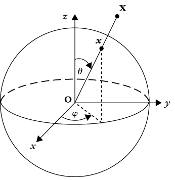
I maintain that sine and cosine can only have meaning within a defined coordinate reference frame.
The sine value is the y-coordinate on the unit circle, and the ‘y axis’ is normally depicted as
the vertical axis. The cosine value is the x-coordinate value on the unit circle and the ‘x axis’ is
normally depicted as being horizontal.
The point being that you need some form of coordinate system.
You can’t arbitrarily label some straight segment within a knot as being ‘sine’ or ‘cosine’.
To do so would make no sense.

I know there are mathematicians who are reading this.
They are remaining silent - and my hypothesis as to why they are remaining silent comes down
to my opening remarks about the concept of ‘harm’. They likely don’t want to hurt your feelings.

My last point - and this is important:
You never apply your world view of trig functions to a standalone knot.
You always appear to use hitches, turns, and various host objects that are integral to the hitch.
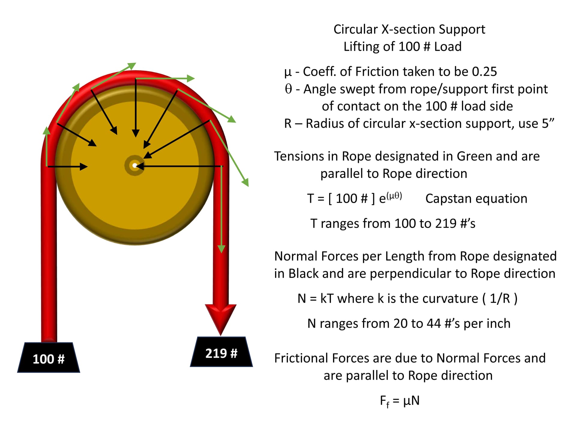
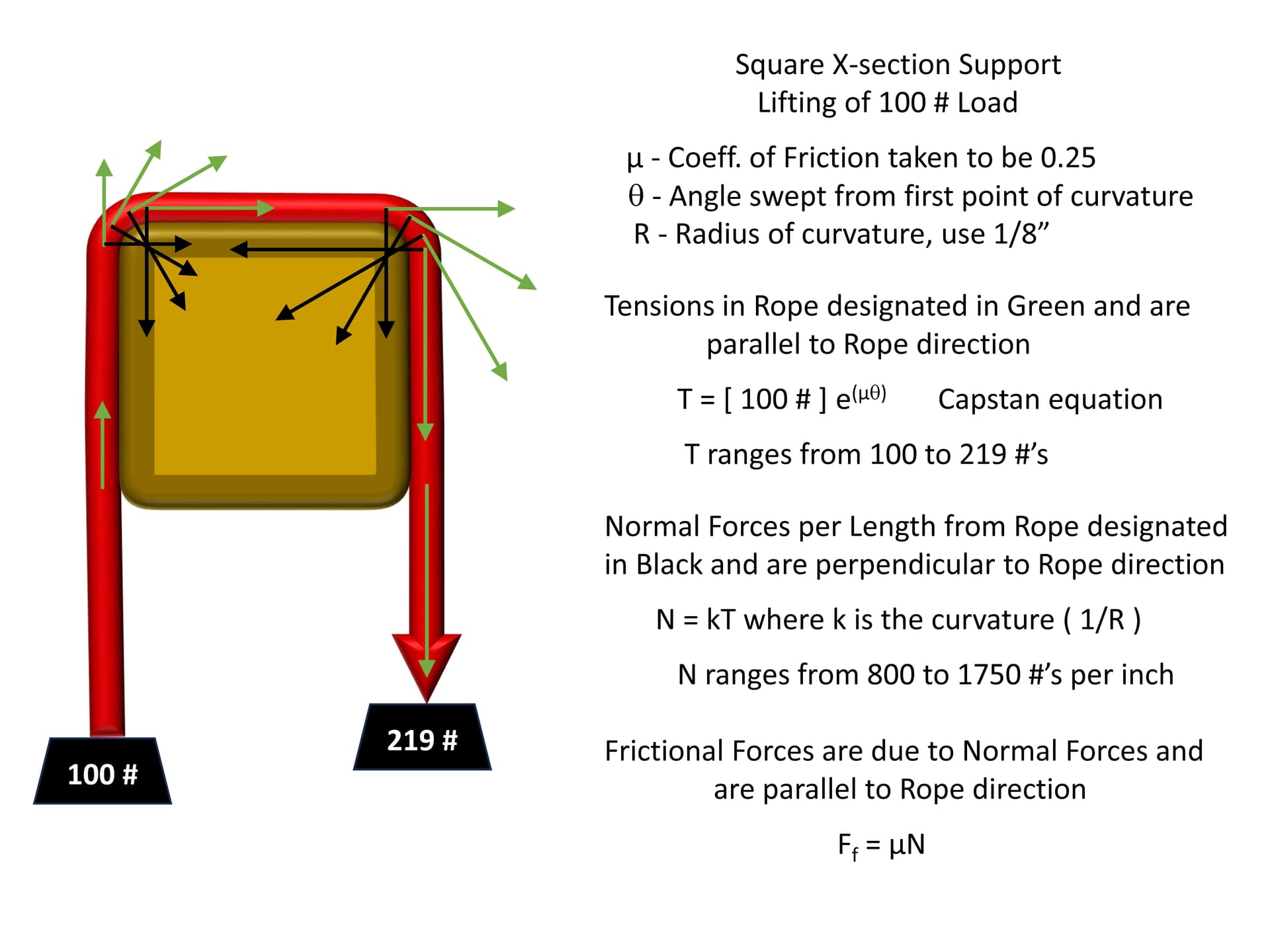
eg; you often use a square profile object and compare this to a round profile object - and provide
various diagrams to show the effect the shape has on a hitch.
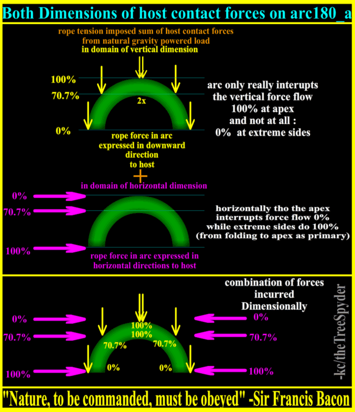
You often refer to the ancients, you show sine wave graphs, and you use various anecdotes to formulate and
share your world view of hitches and turns.

But, as stated, you avoid standalone knots - eg a simple Bowline (which is one of the simplest eye knots).
I specifically chose a simple (#1010) Bowline as a knot that you could apply your world view of trig functions
to. However, you have never shown how your trig functions apply to a simple Bowline.

And this leads to a larger question as to how your understanding of trig functions actually applies to standalone knots?

This is a knot forum right?
The purpose of the forum is to share knots, and explore concepts about knots. Its a forum to exchange ideas about knots.
Mathematical concepts posited on this forum ought to be tied to knots - so the reader can understand the concepts as it
applies to real knots and knotting tasks.
And so I am simply asking you to apply your trig functions to something very elementary - a simple Bowline.
But you can’t seem to do that?

Now i do concede i don’t show (much) in reference to un-loaded ropes; just the rigors and logistics of loaded lines as i have known them best and looked at them hardest. And do look at it as unused rope brought on to the great ships, but called a line when deployed/loaded. Swells in otherwise straight line of Hitch or Bend as nodes(like in plants) of termination of continuation. There is a certain logic to a loaded rope, that unloaded rope doesn’t necessarily follow. As like full of force balloon or deflated, just not the same. Sorry, especially when you showed load numbers on your Bowline pic, thought we were on same page at least on that part.
.
The cos/cause benchmark linear i speak of/present is for ‘rope works’/thread title and also, some of the pics i have stashed at ropeforcelogic.neocities.org, name chosen for the best sense of these things. The sense of order, from loaded rope logistics is my chase, and what i try to claim to know a bit about if i may please. That is why compare to chasing force thru radio that is not dormant, so those elements may define themselves in that domain, when ‘loaded’/enabled with flowing force. Also is like following the force thru the otherwise dormant, unloaded architecture; just like troubleshooting and proving radio. Radio totally different and different study in never on mode(like even balloon) too type thinking.
.
ANY linear can be a cos benchmark to judge other things by, and their specific placement tho. Even unloaded can take vertical Bowline center horiz and vert; call one cos, other sin and calculate every molecule of dormant/unloaded Bowline on a stage precisely.
.
To me, in a working/loaded sense; unloaded rope is in it’s formable state as like warm plastic or metal. But forges to rigid not by cooling tho, but rather loading to make tensioned rigid framework. Rope is a material as like other materials that may displace against distance and it’s reciprocal force; but only in it’s rigid/loaded state. It’s ‘molten’ (even if cotton, manila, jute etc.)unformed state is of little practicality to me and my chase beyond forming , previously to ‘forging’/loading rigid for grit of actual usage. And in grooming/dressing ; urge towards the loaded profile; purposefully placing rope-parts for best build.
.
Using this flow of force path for defining cos gives same answers, i think easier/shorter; and perhaps is even more correct organically. It does lend much easier to chasing properties thru each individual element as i proposed tho as dive deeper into scenario w/o stepping stones/life preserver/boat anchor of having to maintain a static, rigid cos ‘blindly’; not to the organic, dynamic flow.

i think about/L-earn about cos:sin all the time as like going thru individual elements inside a bigger scenario. Driving is one large force example . Forces FELT along long axis of vehicle as cos, to minimal axis across as sin. Pressing into seat and forward as cos, side to side forces to doors felt as sin. Just as speak of feel of cos_0 at end of swing/stroke across as having felt in child’s swing, that breathless stall before return. The relaxed center position as normal resting place w/o motion as the balanced cos between the sin extremes, just like sinewave pic. This horiz analysis also can be found vertically in spring, even engine piston etc.
These references happen and religiously follow the maths; irrespectively where are in 3D space. The only sense of direction system has is it’s aligned force dimension and it’s not/non/non(e). The domain of the alignment and then anything else too, even in hybrid mixes of aligned and not ratios of cos:sin must tell the whole story. All of this and too that which is not, and any (be)tweens.

in animation artist can set the initial and finish positions/properties, and computer can calc the ‘tweens’(actual term) that in earlier years, underlings would create the tweens twixt the major timeline points made by master etc.
.
Again to me Hitch USAGE/not naming convention as a terminating node of single SPart is just easier model to start, dual/dueling SParts of Bend USAGE is just diploid version of increased study then, so i start(ed) w/Hitches as simpler/doorway. But this all specifically applies to all linear rope works(SPart fed force into controlling arcs type usages). The different class to this study is that which is not of focused linear input thru SPart, but rather dispersed radial input directly into controlling arcs without linear SPart usage porting force into controlling arcs. This dispersed radial (rather than focused linear) force input is from Binding against swell, where the force in arcs is not constantly degrading but stable until nips.
.
i say cos xTension etc.; to show cos as the constant(even tho a waveform, a constant waveform) and xTension(or other attribute) as the variable just visiting, riding the constant ‘slide’/waveform of cos. So cos as the repeating constant, even reciprocally as sin, that all rest of influences ‘visit’ as variables. Which i guess is backwierdz of normal..

After much study and cross-discipline and hobby commonalties have found/come to see;

the waveform of cos scale UNIVERSALLY in more than ‘just’ Geometry, as the organic waveform of change.
Though, geometry is a strong representation, as easiest to enumerate and visually see as stepping stone/entrance ramp.
Then, just as take those lessons , numbers from dimensional displacements against distance visually:
then also apply to forces thru the same structure that measure out on scales showing the force.
Then can further extend into, where is already found, studies of electricity, shadow, wind, sound, motion etc. etc.
Then even color gradients of both light/dark gradients of shadowing and also rich color gradients too
that as the most organic, smooth, naturally rolling change look right; because they are..
.
Sine is a natural sway, the epitome of smoothness: it makes circles “circular” in the same way lines make squares “square”.

A sine wave or sinusoidal wave is the most natural representation of how many things in nature change state.
.
“Sinusoidal waveforms are the building blocks of AC circuit analysis.” As they are a smooth, organic change, even at 60cycles a second.
.
Sinusoidal waves (or sine waves for short) have turned out to be essential to understanding how our world works. One example is sound.
.
music
.
Sine waves occur often in physics, including wind waves, sound waves, and light waves, such as monochromatic radiation. In engineering, signal processing, and mathematics, Fourier analysis decomposes general functions into a sum of sine waves of various frequencies, relative phases, and magnitudes.
.

and too then, rope
The 3 minimal elements shown arc0,90,180 are in full observance of full potential expressed at alignment or crossing dimensions

and then directionally when in the same aligned dimension too.
.
Between fully aligned cos=100% and fully crossing=0% we have the same full and null expressions; and thus the waveform of change between
in this Geometry, just like in other things(above); not just a Geometry thing.
Geometry just shares the same waveform of change from full to null, as all else.

It is important to choose an appropriate frame of reference.

CIRCULAR CROSS-SECTION SUPPORT
When looking at the rope partially wrapped around the circular cross-section support, we find that all the forces involved are either parallel (tangential) or perpendicular (normal) to the rope direction at each point in the rope, see attached. This means that the obvious frame of reference at each point in the rope is one that continually rotates with the rope as the rope follows the contour of the circular support. In other words, one could choose the x-direction to always be parallel to the rope direction at every point in the rope and choose the y-direction to always be perpendicular to the rope direction at every point in the rope. With this choice of frame of reference, we find that none of our forces (vectors) need to be decomposed into sine and cosine components.


As we assumed, we see a smooth and continual change in the tensions, normal forces and frictional forces in the rope that is in contact with the support. The force vectors have been accurately oriented and their magnitudes scaled to the maximum value of their range.

CAPSTAN
As we have discussed before, since the tensions and frictional forces are aligned, we find that the tension in each small element of the rope slightly increases or decreases by the amount of the frictional force per length times a small length (arc) of rope section. The frictional force either helps to support or impede the lowering or lifting of the load, respectively. This leads directly to the precursor of the exponential Capstan equation ( change in Tension ) / ( Tension ) = ( Coefficient of Friction ) * (change in angle ).

SQUARE CROSS-SECTION SUPPORT
One can do a similar analysis for the square cross-section support if it is assumed that there is some small radius at the corners, see attached. Of course, the validity of such an analysis must become increasingly suspect as the radii of the square corners become much smaller than the radius of the rope.

Once again, we find that all the forces involved are either parallel (tangential) or perpendicular (normal) to the rope direction at each point in the rope. We again choose the x-direction to always be parallel to the rope direction at every point in the rope and choose the y-direction to always be perpendicular to the rope direction at every point in the rope. And as before, with this choice of frame of reference, we find that none of our forces (vectors) need to be decomposed into sine and cosine components.

In those rope sections where there is no curvature, the tension in the rope is constant and the normal forces and frictional forces are zero. All of the changes in the tensions, normal forces and frictional forces occur at the corners. The maximum tension in the rope is the same as seen with the circular support because the Capstan equation is independent of support radius and the ropes in both supports sweep out Pi radians (180 degrees). The force vectors have been accurately oriented and their magnitudes scaled to the maximum value of their range.

DDK

TY for your input AikBkj,
i totally agree about the corner frictions of linear faces. Corners as deformations from inline flow(cos) to give the Frictions(sin of 70.7% from each parent leg of force when 45° apex of a 90° corner). The Linear parts 100%parallel to Linear host face(cos) ; then leave nothing to power the Frictions(sin). It is the deformation from the Linear(sin) run that give the Frictions, not the pure Linear(cos) itself. Linear is simplest flow form, and can only simply handle to use cos or sin for Load or Friction(if hits facing). Not both at one time, for is only 1Dimensional in it’s usages.
(perhaps could say the same as your parallel vs. tangent break down of same Dimensional influences in the end.

i also totally agree for ranged spans of Capstan Frictions and Grip, we don’t need to break down to cos:sin :open_mouth: (surprise). I sincerely don’t numerically..
BUT, i do realize them as defining the Dimensional powers behind arc Frictions and Grip as they do for all things. So realizing the patterns of forces define why these 2 uses are so powerful compared to other usages AND how the arc Frictions and Grips fit into the rest of the all as maintains single defining concept for all of them. In rope utilities of nip and preservation of strength/efficiency, linear frictions, corners etc. cos:sin can reveal reveal more than just flow pattern, but actual amounts directly related that are more usable.

Realizing the force pattern on an arc and how well it is used on spanned ranges of Friction and Grips; grant greater respect(vs. other loaded geometries, just like bridge arc180) uses and understanding of these forces. No other geometry uses the forces as well, as an arc where the endpoints and even apex pull not only in same Dimension, but same Direction!! And to do so over a range of Friction (or Grip that takes an opposing rope for full cos+sin effect). :
both-dimensions-of-host-contact-forces-on-arc180
A single arc180 only gives Grip on crossing axis/Dimensions(sin); but another rope part as an opposing arc180 gives Grip on both Dimensional axises(cos+sin). Even in Round Turn(RT); that has 2x arc180s and only single opposing arc180 .

In the end, the groups of these definitions from these Dimensional influences , lead me to see/look for the 3 rope elemental geometries of arc0,90,180(where arc0 is the non of arc)