Model/Prism of only 3 repeated root elements for organic/cornerless rope works

Looking at a corner as an immediate, forced, un-natural, inorganic, flow interruption;
vs. the more natural, gradual, organic flow of arc for best architecture when loaded.

Other than in-organic corner, the 3 elements are : linear(0 degrees) and 90degrees, 180degrees arcs.
Actually i look for them in reverse order, starting with ‘most evolved’ arc180?.

as much a marvel in this usage as for bridge or Roman Colosseum, for same reasons.
Then 90s, to find arc0s/linears remaining


.
Rope is a material, as like other materials, of attributes that can be enumerated.
As universally with other materials, geometric dimension and direction of input;
determine how fully and where finite input can be expressed or not.

Thanks KC.
I put myself in the shoes of a layperson / casual reader, and from that
perspective, its hard to make sense of what this theoretical information
is intended to apply to?

A layperson would (maybe) make a wild guess and assume that you
are thinking about hitches?
But that might depend on whether a layperson actually has a working
definition of what a hitch is?

Its difficult to see how this information might apply to a knot:
(a knot being a self-supporting structure that has an intended
distinctive geometric form, which enables it to be recognised).

I surmise that perhaps a “Round Turn and Two Half Hitches”
might fit the intent of your post?
The ‘Round Turn’ being performed around a ‘host’ (eg a pipe),
and the 2 ‘half hitches’ being performed around its own
Standing Part (S.Part).

We know that hitches don’t work so well around square profile

  • round profile being optimal. That is, the shape of the ‘host’
    matters.

I see that you persist in using Sine and Cosine as part of your
narrative. Your use of these trigonometric functions makes
no sense.

In trigonometry:
cos 90 degrees = 0
sin 90 degrees = 1
These values are based on the ‘unit circle’.

A more realistic mathematical analysis of what’s going on
within a ‘hitch’ might involve the capstan equation.
Although, the capstan equation does not include the effect
of crushing/squeezing (eg one rope segment squeezing/crushing
another encircled segment).

I would also comment that you don’t appear to examine ‘knots’ - you
appear to have a bias toward ‘hitches’.
For example, I’d like to see your theoretical analysis applied to
a Zeppelin bend - and perhaps explain why it is resistant to jamming.

Dr. Smith, et al…
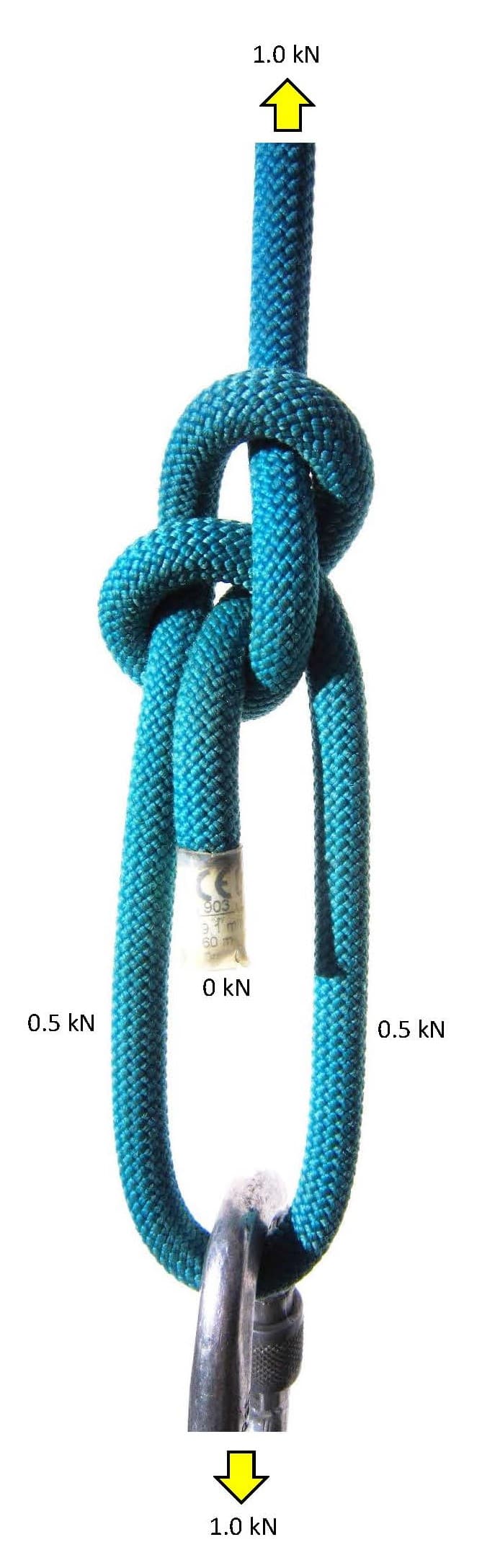
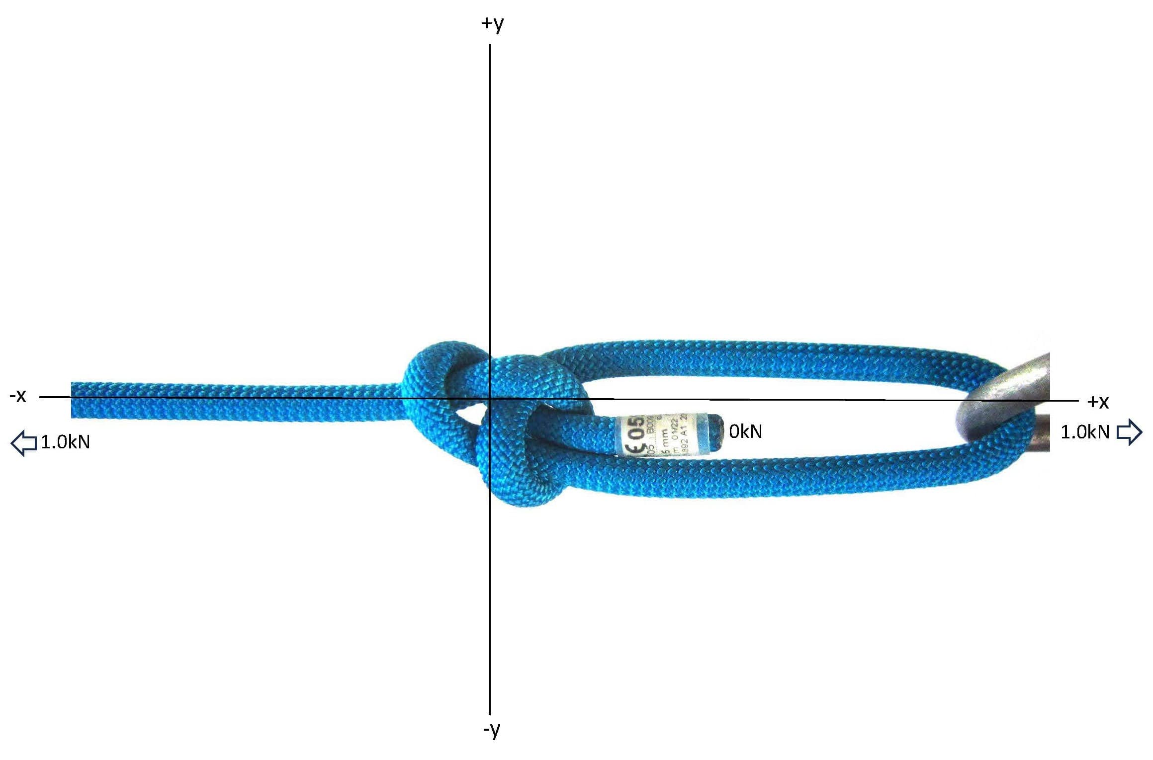
i show this for all knots, ropework; but simplest to start with Hitches and Bends that port linear force thru a SPart/Standing Part into the receiving ‘knot’ microcosm, whether it be termination(Hitch) or continuation (Bend) at the given node swell (from otherwise clean running/flowing rope line).
.
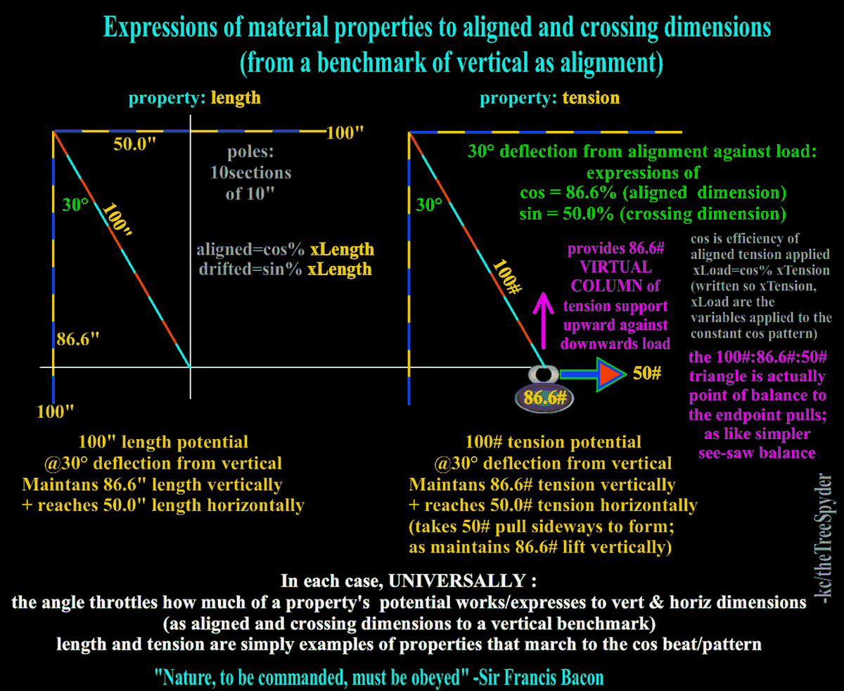
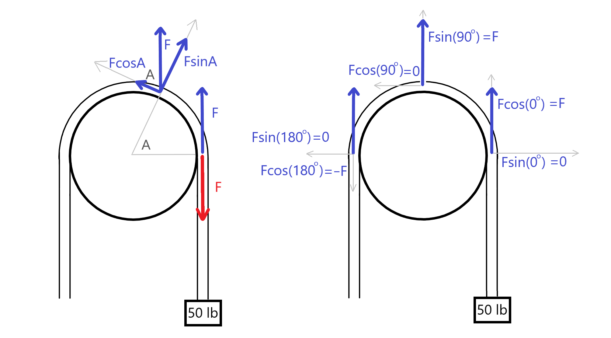
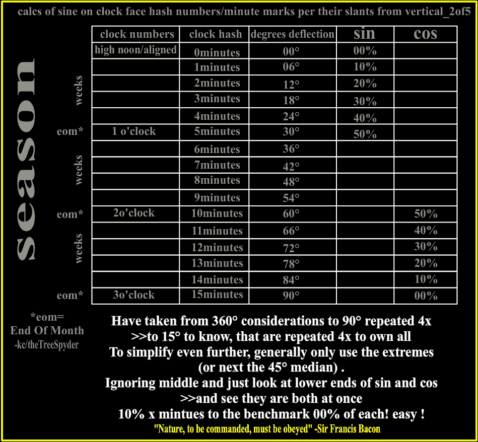
Pure alignment vs. pure 90degree crossing from that benchmark alignment of input force direction are the separate dimensions needed to enumerate by cos:sine patterned %'s ratio. 100%pure cosine is totally devoid of any sine, vice/versa. Anything between these dimensions of pure alignment or 90degree crossing to alignment has some of alignment dimension and some crossing dimension at play, decoded to cos:sine percentages of the available potential to the crossing dimensions of consideration.
.
This proposed model/prism of view for 3 organic rope elements uses cosine/sine in real world more dynamically tho than fixed un-dynamically to a horizontal axis statically; as introduced in school sterilely on graph paper.
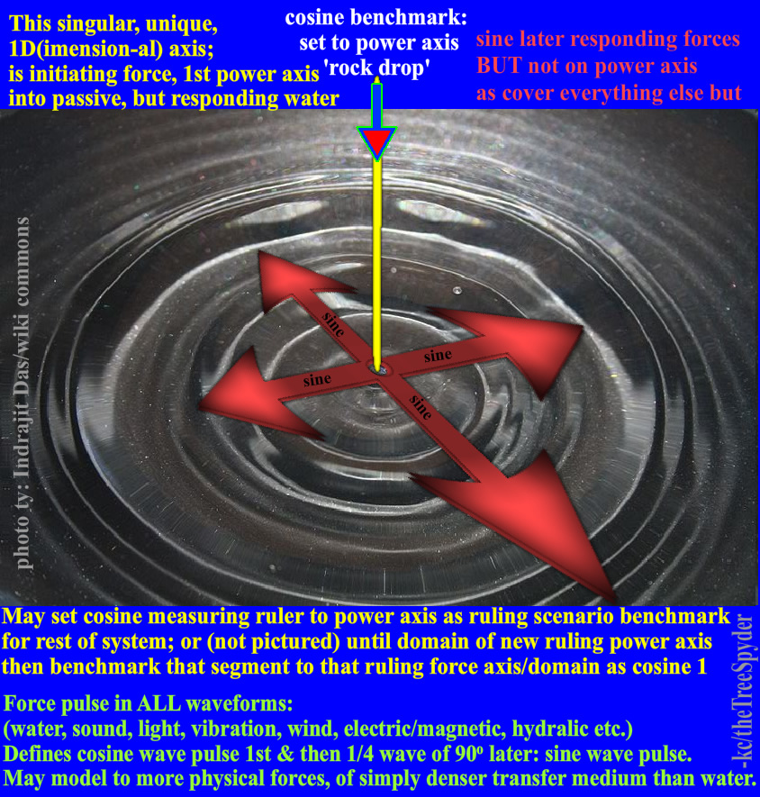
This cosine usage looks at where an aligned bullet should go as sighted(w/o drift) and the recoil together as cosine benchmark of most loaded axis formed by these opposing directions(bullet and recoil paths). Any value from drift of projectile down, up, or to any side is revealed by sine as drift from the original benchmark cosine of most loaded axis.
So dynamically can set cosine benchmark to the projected pure linear (force)path; anyplace/angle that firearm is set to. Firearm does not have to be horizontal to show cosine, as it’s force defines the cosine benchmark if bullet path is what we are tracking etc.
Same could be said of this vertical stone drop to calm waters, to give the resultant sine waves outward from the benchmark cosine linear axis(vertical w/cosine hear) :


The vertical stone drop is the unique benchmark cosine axis, sine/waves as drifts from unique benchmark cosine axis. Full considerations of alignment and deflection(s), as in all things.
.

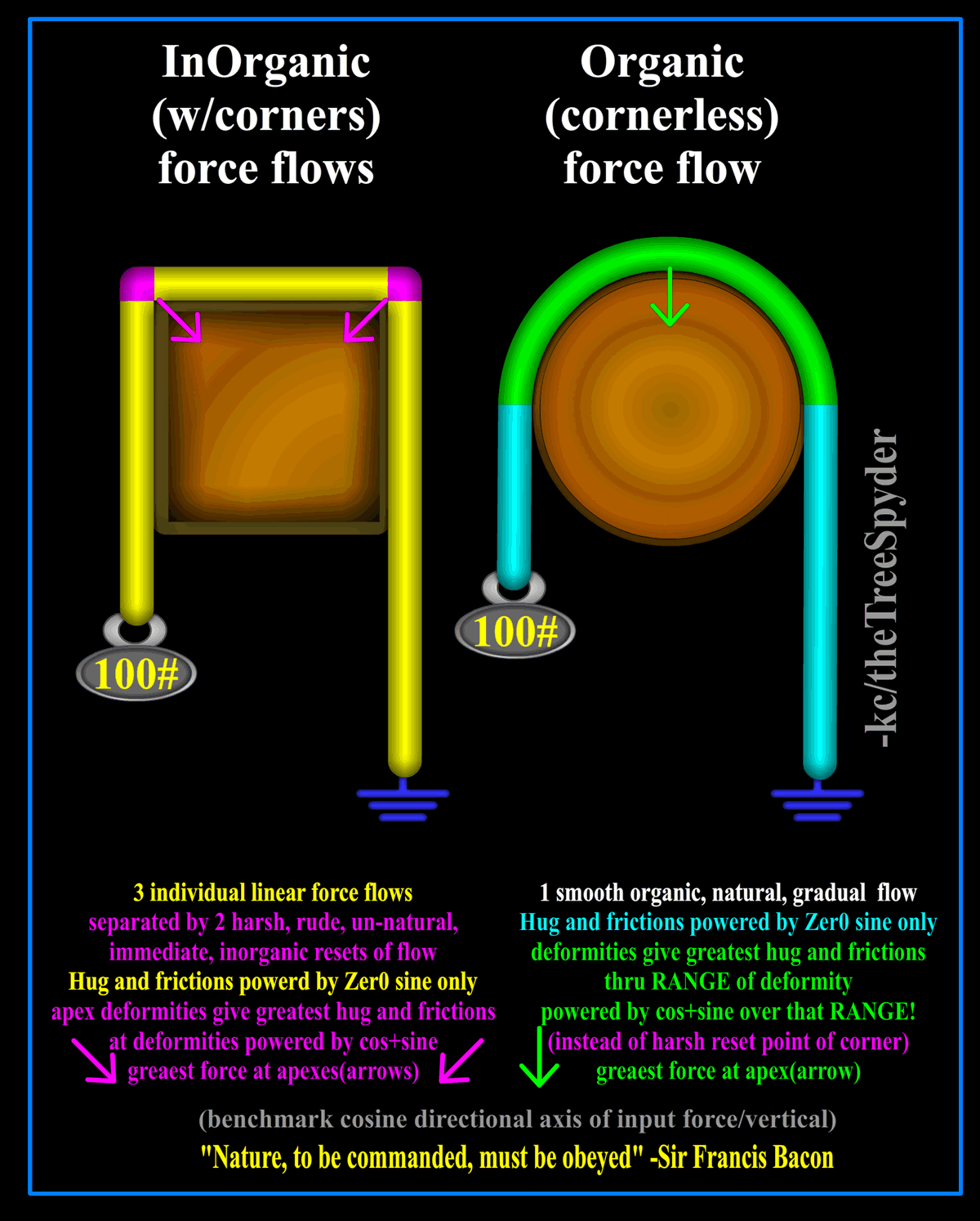
TY, this is my why to that, and how it fits into this model; as projects forward for workings of triangular or even octagonal stop sign shaped geometries as hosts, and where friction is/isn’t in these models.
Also, should always view things as focused linear/s(where corner is not travel but rude/sudden/inorganic change) or dispersed/unfocused radial of organic gradual change. Flat rope has thus a focused linear cross-axis of consideration in contrast to round rope’s evenly dispersed non focus; as far as same considerations for same reasons of rope material around linear of radial faced host encompassed.
.

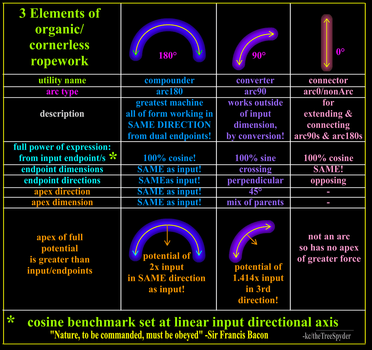
The capstan equation is part of the root of this model for the frictions, as also capstan theory highlights the most evolved arc180 element of building an architecture in rope; just as in stone bridge. Also, it is my contention that the capstan equation w/o the friction value logically leaves the seating value of the rope to round host, This seating value gives hug/grip when operating on both sides of host in opposing directions across; arc180 again superior for the reasons i tried to highlight(only need arc180 on both sides for full effect). It is all the geometry, as like in arc bridge and glass bottle sides etc..
.
For these forces as shown here in rope, are really in all things; and when enumerated to graph show same in gradient fades of light, vibration, wind, electric etc. All are the same patterned graduated rate fade from dimension of full potential to their dimension of non(e) of that same enumerated attribute potential, universally. Rope is just 1 facet to view central works of same gem of how all this stuff works. The receding cosine makes up it’s own factor of economic “Law of Diminishing Marginal Returns” to this predictable path.
.
Things change by rigidly displacing against their non. Occupied space can displace against it’s non of freespace as distance; or against a non of equal/opposite displacer as force. As cosine rises, sine decreases etc.
Rigids may resist in 3 dimensions, and in both tension and compression directions in those dimensions.
Rope, as a flexible device, offers it’s lessons in some ways simpler, in that it only natively resists force along it’s length dimension and then only in the tension direction of that dimension. Thus , fewer considerations to rope, except perhaps counter-intuitive idea that a flexible(rope) can rigidly displace against anything!
.
These rules shown are UNIVERSAL, that miniscule Earth must then inherit even to our humble rope, even all atoms and their electrons. These things are so innate to us, that if the calculations of change for motion, speed, sound, light, shadow etc. do not follow these patterns, they fail as Virtual Reality. The deep, inner, lowest level of brain can tell are out of pattern, and said gatekeeper is not drawn into the ‘immersive’ level that VR can lend. We are so surrounded and saturated with these things as normal base, we cannot just simply see them separately anymore than a fresh mold spore on petri dish can taste the gelatin. The gelatin is just that which is to the mold spore, there is nothing without it to it; it is just that which is. The cos:sin patterned ratio is like that to us i believe; as has no non.
.
Peace.

Agent Smith !
-et all;
i think these are key factors not to miss, please.
Aligned dimension% vs. opposite of perpendicular/crossing dimension% reveals in value pair ratio cos:sine.
Applicable as reach and support column% : byproduct of host hug (for frictions, nips and grips in rope)!
Been trying to get more time drawing etc. figured would just post what have.
.

.
Sorry, cannot leave this behind; i totally, completely disagree; and really find that value pair cos:sine are the key definitive here, and everywhere.
This is an Universal pattern shown in these numbers; viewable now from front row seat of raw rope work, that could be taken as fairly simpler model of cos:sine ratio of expression in everything.
.
i model 100% efficient virtual column as correctly aligned to maintain support column constitution longest against load, breaking only at highest/peak capacity tensile strength possible, cos=1; so 100% as benchmark potential. Physical column may slant/deform to lower % virtual column constitution maintained against load as force vs. perpendicular dimension of shear across to destroy that same support column by contrast; so breaks at lowest possible load; as extreme yin/yang contrasts of influences to the sum of the total whole. So as to reveal both sides of coin at once, even during the flip.
.
The cross axis load of support (sine)is as byproduct co$t of achieving needed support on aligned axis to load

so loss of cosine as efficiency costs more input to same target; AND carries greater cross force byproduct cost to be carried at same time both challenging against efforts
pure aligned cosine 100% has no byproduct; sine=0% ; so no host hug side force for frictions, nips nor grips.
cos:sine in ratio to support column:hug as giving force to frictions, nips and grips.
Trade-offs of how much of total sum tension is expressed to the 2 parent dimensions of aligned vs. not aligned(crossing),

Several standing common examples of tensile strength lost or maintained per support column deformity of SPart input to similar knot architectures:
A HH shears across the single column of support harshly, but Tensionless Hitch does not.
A Cow/Girth shear across the SPart(s) too;

but less so when sporting ‘bull nose’ on either
that i think grips around SPart(s) to pull more correctly along the SPart(s) as a column, rather than just shear across as less evolved Cow/Girth as spreads out contact.
So we can see that a simple single Turn/arc180 is a 1D pull shearing across SPart column or other host, 2xarc180 gives 1D grip around, and a 3rd arc180 for RT ‘component’ architecture of more 2D grip and higher tension reductions from frictions*. Here it’s utility of grip serve to comb/pull/groom more along the SPart support column ‘properly’(cos), as also reduces forces across(sine) same support column(s).**
.
Cat’s Paw and Rat Tails take it a big step further; almost lacing a re-usable splice the way they pull along, not across the support column(s) to maintain cos, to your cause(support).
.
A simple Turn around host and Friction Hitch(FH) back to SPart column can help keep ‘clean’ column; the pointier the ‘teepee’, the more strength maintained. But less hug as a trade-off of higher cos:less sine.
Round Turn(RT) on host before FH can help resolve, but then less power in FH grip from the lowered tension.
These are trade-offs incurred in the manufacture of the ‘device’ made of the rope architecture at rigid/tension loaded.
.
This is not just about the strength/tensile preserved tho, but rather the pattern used to express in aligned vs. crossing dimensions, that also find in rest of things, as the Ancients tried to gift down/forward.
Organic/Natural fade from full potential (as a dimension) to the opposing non(e) of potential is always same pattern. Even with organic fades of sound, light, electric etc. fades to non(e) on graph.
.
Distance and therefore reciprocal of force(potential distance unachieved) are just most visible parts of this deep iceburg of pattern.

*A key component in may things, even bringing Cow/Girth to Prusic’s open or closed, by RT not single Turn to each side etc.

**Kellig is interesting ‘twist’ on pulling more along columns, so less shearing across;

but also can tweak/crank rope, especially if stiff/rigid organically and/or rigid at high load, so like kink in chain can count against efforts to maintain strength. Does not flow so cleanly as unkinked finds subject to more/easier/earlier ‘corruption’ of column constitution. Some varying trade-offs to be suspected here.

My contention offered is that these things shown below happen to all things, UNIVERSALLY;
as we can show them outside a Hitch, the universal pattern ruling even the stars;
then doesn’t stop at knot node border as disappears inside the Hitch’s microcosm.

and rope’s property of tension powers the knot node w/these forces; to these numbers (less any frictions) as travels around.
.


.
i use potentials of length and force here that match; so can see they change in co-ordination as angle changes. Then set to 100units of whatever to show cos as root math most clearly. Pattern continues to follow cos scale even when length and tension don’t match, and are not such an even clear number to play with as follow them thru the visual model of Geometry.
.
Geometry does give a visual, enumerated example of fades from full expression of potential to none that are found also in physical, electrical, light, vibration, wind, water etc. force changes. That then give the range of all possibilities of expression of each principle’s individual expression, and where in the range of change they happen. Just from knowing the extreme endpoint positions of full and non, hear is gifted the rest of the ‘tweens’. (tweening: making transitioning images from a ‘keyframe’ to next in animation as to show change/action/movement, the time slices betwixt).
.
The organic gradient fade of a property from expression of it’s full potential to non(e) always follows the cos scale.
It just so happens that this also applies to going from fully aligned to fully crossing in geometry, but goes much further beyond those most visibly enumerated points.
.
“The world is full of magical things patiently waiting for our wits to grow sharper.” ~Bertrand Russell

.
Been kinda leaving this alone, but i think misleads greatly.
Have started typing this over and over, so much to say; as we just glance at part of the visible tip of this iceburg.
i find these presented concepts as Universally defining; and go much deeper than this model as then a beginning and not an end.
.
cos as alignment to cause(cos/mnemonic)
Model Cosine as benchmark alignment vs sine as non(e) of alignment(drift sideways to full crossing) is key to decoding scenarios. For the model reveals the precise ratios of natural, gradual(organic) change thru all possibilities from 1 extreme (pure alignment) to the other (pure crossing/non-alignment) and ‘hybrid’ positions between these 2 parent extremes. These things work on geometries of applied distances(reaches) and the distance traded/reciprocal that are forces. Change is rigid displacement against the non(positively or negatively), geometry offers these values to show logical end.
.
cos of a material is then the cos of properties(or attributes) like reach to load and support against load
If round material rope is at a 30degree slant/deformation from pure inline, it will only express 86.6%(cos) xPotential to the original aligned dimension of a hanging load. So if matching(to show consistent pattern most clearly) attributes of 100units length and 100units tension as potentials, at 30degree deflection, it will only reach and hold in the aligned dimension Load 86.6units each(cos of 30degrees): reach to and load support. When look at 2leg sling span ratings by degree, this is how it is calc’d by cos of support legs in load/cause dimension.
.
mono-axis Linear(focus) vs. multi-axis Radial(dispersion)
Linear force is to a single, focused axis from a center; while radial is dispersed to multiple equal axises from a common center. Circle takes this to a full 2D dispersion of all possible 1D focused axises. So it is just mono vs. multi axises we see with linear vs. radial, as focused to 1D or dispersed to more.
.
Hitches( and Bends) have Linear Force as source type, because SPart is a linear and ports the force to the radial arcs(typically)
No friction(or other seating value) to host, w/o rope deflection from pure inline load by host. In linear deformations cos is used to load dimension and sin is to crossing dimension(for host frictions, nips, grips). A deformation, by host, from linear around a corner gives cos+sin xTension at that point, as like Nip does/to a single point. Arc gives greater cos+sin frictions tho, and organically over a further flowing range!!!
.
Hitch and Bend USAGE port Linear, focused 1D rigid tension thru SPart(s) into the magic of the controlling arcs of radial dispersion.
i show mostly Hitches on this, but just as the simpler mono-SPart form, not to exclude dual-SPart form of Bends. SParts are the inputs, and may only carry Linear Force. Deformations from the input Linear Force, especially Radial conversion as a range of conversion from input of Linear Force are the real force manipulators and utilities. Linear parts, are more just connectors over distance as their magic, connecting the power of the deformations/arcs. Trucker’s Hitch etc. is same power fully or only half extended; because only the linears change, and the real manipulators of force are the same at half or full extension .
.
Friction as a co$t of conversion from Linear Force input to Deformity or Radial control
The deflection/deformation from pure linear leaves material less effective in aligned dimension potential as adds more to the crossing dimension potential to give friction etc.. Per the cos/sin Universal ratios of organic change thru the deformation from simplest linear.
.
example: Constrictor/Groundline/Bag fam
can all be used as Hitches and so show the degrading rigid tension from full(SPart), to decreasing(lacing) to none(Bitter End). Same lacing used Binding against round swell has zero rigid tension at ends and full rigid tension equally for a span, between nips(not gradually degrading). The Binding is radial controlled too, but also radial force fed; so equal tension thru active parts between nips as no conversion loss in radial input to radial control(like find in linear to radial of Hitch or Bend USAGE/not per naming convention).
.
Super power in Capstan Theory
From the Capstan theory; i L-earned to count in arc180s; a stroke in standard gas engine speak.
Also, found that arc180 is the most evolved of what i see as the 3 directional elemental rope forms (arc0/linear, arc90/converter, arc180/compounder).
i think if we remove the friction multiplier from Capstan Formula exponent, we logically have some form of a seating to host factor formula remaining. That applied when arc180s on opposing sides gives grip. Powered by same forces as friction, w/o the friction..
.
Math helps reverse engineer scenarios to decode to consistent definition of deepest common/pivotal elements, then can competently forecast foreword as well as forensically. Like taking this from static examples to dynamic/motion examples(pendulum, spring, piston etc.).The language of Math is consistently logical in providing these services.
The only thing pivotally deeper to fewer parts than cos/sin duo; is the event itself.

Quote from: agent_smith on October 07, 2024, 01:47:35 AM I see that you persist in using Sine and Cosine as part of your narrative. Your use of these trigonometric functions makes no sense.

In trigonometry:
cos 90 degrees = 0
sin 90 degrees = 1
These values are based on the ‘unit circle’.

A more realistic mathematical analysis of what’s going on
within a ‘hitch’ might involve the capstan equation.
Although, the capstan equation does not include the effect
of crushing/squeezing (eg one rope segment squeezing/crushing
another encircled segment).

I would also comment that you don’t appear to examine ‘knots’ - you
appear to have a bias toward ‘hitches’.
.

Reply from "KC": [b]Been kinda leaving this alone, but i think misleads greatly.[/b]
"Misleads greatly" - really?

What your epistemological source of truth and meaning of trig functions?
Mine is derived from the unit circle and the universal relationship (and ratios) between angles and lengths of sides of right triangles.
Here is a video that explains some basic truths:
Link: https://www.youtube.com/watch?v=uMfnJ6TJinc
And for non-right triangles: https://studywell.com/trigonometry/non-right-angled-triangles
A good general overview is here: https://www.youtube.com/watch?v=vuoNyvMvDtA
As Sine goes from 0 to 90 degrees, at 90 degrees it = 1.
As Cosine goes from 0 to 90 degrees, at 90 degrees it = zero
Sine 150 degrees = 0.5
Cosine 150 degrees = 0.866

KC, if someone disagrees with you, is that hate speech?
That is, is mere disagreement sufficient justification to label your opponent as being misleading?
Do you accept my epistemological source of truth and meaning regarding sine and cosine? (Yes / No)?

I had asked you previously to apply your definitions of sine and cosine to an ‘eye knot’ - eg A simple (#1010) Bowline.
You have never shown how your understanding of sine and cosine applies to a simple Bowline.
What you always seem to do is model your theories around hitches (which require a host).
Why is that?

Challenge to “KC” (this is not hate speech - it is simply an opportunity to apply your model to a fixed eye knot):
Using a simple (#1010) Bowline as the objective knot, apply your sine and cosine model to show how the knot
resists slipping apart under steady application of constant load (for the argument, lets set the load at 1.0kN.
In addition, using your model, show how force propagates through the Bowline structure via the S.Part and opposing
eye legs.
Force is measured by a calibrated digital load cell in the following way:
The load cell measures 1.0 kN at the S.Part, and 1.0 kN at the tip of the ‘eye’.
The load cell measures 0 kN at the tail end.
Show your coordinate system so I can see how you derived Sine and Cosine values throughout the Bowline structure.
Please use the attached image as a reference for your model.


Bowline_Loaded_1kN_WEB.jpg

I am not sure I totally understand either, but here is my attempt. First, Mark you have one minor error in the last reply. While sin(1500) does equal 0.5, the cos(1500) is the negative of one half the square root of 3, which is approximately -0.866.

In my diagrams below, I assume that a rope goes around a circular object and that there is a weight on one end. That weight causes a force that I have labeled with a red arrow, and I assume it has magnitude F. If nothing moves, there must be an equal and opposite force labeled with the blue arrow with the same magnitude F. I can only assume that KC intends to find the components of this blue force at other locations in a local coordinate system (light gray in each case). Thus, when you move around with angle A, the two components have magnitude Fcos(A) and Fsin(A). In particular, Fcos(A) is always the tangential component. I do not believe that this tells us much about what is happening to the rope at these locations, but we would need more information about what is involved to keep the rope from sliding around the object to understand all of the forces.

In the second diagram, I show some special cases of angles.


Sine and Cosine Forces Explanation.png

In my diagrams below, I assume that a rope goes around a circular object and that there is a weight on one end.
Irrelevant to my challenge at reply #6.

I’m not sure if English is your first language (this is a genuine question, not intended as an insult)?
Language is important - because words have meaning.
If we cant sort out our definitions, we will never reach any form of broad agreement.

I had challenged ‘KC’ to apply his use of sine and cosine to a Bowline.
It is axiomatic to state that there is no cylinder or any host object existing within a ‘Bowline’.

My challenge is re-stated as follows:
‘KC’ always applies his mathematical model to a hitch or turns.
Definitionally, a hitch requires a ‘host’.
I have never seen ‘KC’ apply his model to an ‘eye knot’ (a standalone entity that requires no host).

You (ie Dennis Pence) have adopted the same repetitive approach as ‘KC’.
You both have posted a reply based on a hitch or on turns.

Why is that?
Its an interesting question!

I do not believe that this tells us much about what is happening to the rope at these locations, but we would need more information about what is involved to keep the rope from sliding around the object to understand all of the forces
And this tells us almost nothing about what is going on within a simple Bowline (Ashley #1010).

Mark,

No offense intended or taken. Yes, English is my native language (I was born in Indiana and now live in Michigan in the United States). Thus, I have a mid-west accent among the many dialects even in the United States. I know this is a little different from the use of English in other parts of the world, including Australia which I got to visit last November on a cruise ship and a short land tour. (Our ship stopped in Townsville, and we visited the Billabong Sanctury.)

I agree that this discussion has very little to do with what happens in a Bowline. I was just trying to come up with some explanation for how the sine and cosine can come up when people try to analyze forces. I will now stop trying to contribute to this discussion, but certainly analyzing the internal forces involved when you tighten and put stress on a Bowline will be extremely challenging. When you do, the tangential component of those forces may play a role.

I had a college minor in physics, so I can understand most of what might be presented in a force analysis. I am retired now, but I spent over 40 years teaching university mathematics, particularly applied mathematics. I have taught trigonometry many times in my teaching career. I do know that subject fairly well.

Dennis

Thanks for your prompt reply Dennis.
This is good because as you know, we haven’t met (face-to-face) and don’t know each other on a personal level.
Now that I know that English is your first language - I feel more comfortable engaging with you at a higher level of knowledge.

I spent over 40 years teaching university mathematics, particularly applied mathematics. I have taught trigonometry many times in my teaching career. I do know that subject fairly well.
Excellent. I would like to appeal to your mathematical background please. Please review the attached image below. [u]Questions:[/u] 1. Is the Bowline 'eye knot' appropriately oriented within the x/y coordinate system? (ie I aligned the 'x axis' along the S.Part). 2. If the orientation is incorrect, please advise a preferred orientation. 3. Am I correct to assume that a reference frame/coordinate system is required to enable trig calculations? That is, can 'KC' make trig calculations without a coordinate reference system? 4. Within the reference Bowline knot, is is possible to track the propagation of force as it goes from 1.0kN at the S.Part to 0kN at the tail end? 5. Along any segment of the Bowline knot, can 'sine' or 'cosine' be applied based on whether it is a [i]curved [/i]segment or a [i]straight [/i]segment? Commentary: It appears that 'KC' is positing that a vertical straight line segment is (quote) [i]"100% cosine and an arc that scribes 90 degrees is 100% sine"[/i]. Can such a declaration be made in terms of a Bowline 'eye knot' (Note: There is no host object within this knot). Please provide your commentary/opinion. [u]EDIT NOTE:[/u] I am of the view that it is not possible to declare a particular segment within a knot as being 'vertical' or horizontal' per se. That is, the concept of 'up' and 'down' is arbitrary in my view. Thought experiment: Astronauts aboard the ISS space station have no concept of 'up' and 'down'. If an astronaut tied a simple Bowline, there would be no way to declare which segment is 'up'. The astronaut would have to establish a coordinate reference frame, and orient the knot within that reference frame in order to define 'up' and 'down'. [b]Q. Am I correct in this hypothesis?[/b]

Lastly, can you:
6. Succinctly summarise a layman’s definition of what ‘sine’ and ‘cosine’ is?
7. Is the use of trig functions a useful and appropriate mathematical tool to explain how force propagates through a knot?

I thank you in advance for your assistance in this matter.


Bowline_X-Y graph_loading_WEB.jpg

Mark,

Here are the answers to just a few of your questions. First the orientation of the axis and the location of the center do not really matter. Mathematicians always locate them as you have it, and physicists always locate them so that things are easier. You have the advantage of rotating and moving your object to get both things accomplished.

The only reason simple trigonometric functions apply would be in situation where the “path” of the rope is a perfect arc of a circle (remember you called them circular functions). Still when the path travels in arc which is nearly a circle, the forces will act nearly like this. What you really need to do the analysis is a mathematical parameterized description of the path of the rope. Then you can use calculus to find the tangent direction at any location. Sine and cosine functions easily provide that parameterization for the arc of a circle.

When there is a solid fixed object, that object applies force to the situation (equal and opposite) to prevent motion. For example, your Bowline might be attached to the ceiling. Since the ceiling does not move, it provides this upward force for the standing part. There is perhaps a weight attached to the eye, so gravity supplies the downward force. Various testing machines usually have one end (say on the left) fixed and the other end (right) mechanically applying a measured force.

More complicated are the resisting forces when the rope is tied around an object. Suppose the rope attached to the ceiling is tied round a short tube of metal in a Clove Hitch with a weight attached to the free end. Suppose the tube is not attached to anything. Still the sides of the circular tube resist motion inward. The nipping loop of the Bowline is tied around the two legs of the collar and perhaps one or more rope parts in the locking structure. The interior rope parts act like the tube to resist inward motion. But they are not truly a solid object. Thus, as they first begin to receive inward pressure, they do not provide enough resistance to prevent inward motion. Eventually as they compress a little, there is enough resisting force to stop motion. I would not want to try to mathematically model that!

The real trouble scientifically analyzing a knot is understanding friction. Most knots depend upon friction to hold. Now friction and air resistance are terribly difficult to model mathematically. Physicists and engineers always start with very simple models for friction, and they use them as long as they provide reasonable models. When the models do not reflect reality that occurs, then they move to more complicated models for how friction behaves. We have seen in the knot-tying world how knots that were fine with natural fiber ropes (with greater surface friction but less internal strength) now no longer work well for the new synthetic ropes (with less surface friction but stronger internal strength, so they can be thinner). Again, I would not want to attempt a mathematical model to accurately describe this, but we can still seek to deal with it. Instead, we do actual physical tests to measure as many things as we can, and most of these results depend upon what rope you use in the tests. Even Ashley did his own physical tests (see page 17).

I don’t think that I can explain trigonometry in a few sentences. The origins of the subject go back to ancient astronomy. It is easy to understand how angles play a large role in attempting to understand where the objects in the sky (sun, moon, planets, stars) with be located in the future. Some similar things turned up in attempts to do simple surveying tasks on land. It actually took a while for there to be agreement about the definitions of these functions which are so useful in describing things that happen in the real world. It is easy for mathematicians to define things, but these things only stay around and become important when they find interesting applications. Then we (mathematicians) get to teach them to other people who need to use them. Try taking a short course on trigonometry if you feel you have a need for it. There are some free ones on-line, but I am not familiar enough with them now to recommend one (and they come and go frequently). The one difficulty with these short (and even some longer school) courses is that they may not take the time to show interesting applications. If you really want to use the subject it is nice to see some of the applications as you learn (even if they may not be your ultimate intended applications). I would not think trigonometry would have too much application to the study of the internal forces within a knot. However, there would be lots of applications for understanding pulleys and the other rope systems for climbing.

Dennis

Thanks Dennis,

I think we need to flip this around.
I actually understand the mathematical concepts quite well.
I should have made it crystal clear that I needed you to direct your points toward ‘KC’ and his epistemological position.

The idea was to demonstrate how sine and cosine can be directly applied to a standalone ‘eye knot’ - ie a simple Bowline (Ashley #1010).

'KC" always posts his theories around hitches and turns.
I have never seen him apply his model to a standalone knot (with no host).

I fielded my questions specifically in relation to:

  1. Curved segments verses straight line segments within a knot (ie Bowline).
  2. The notional concept of ‘up’ and ‘down’ (using the thought experiment of an astronaut aboard the ISS space station).
  3. The propagation of force through a knot as it goes from 1.0kN at the S.Part to zero at the tail end.
  4. ‘KC’ appears to posit that an arc that scribes 90 degrees is somehow “100% sine” and a straight line segment is somehow “100% cosine”.
    I wanted your opinion on how ‘KC’ can make such a claim.

As for the other commentary on whats going on within a standalone ‘eye knot’ (ie Bowline):
I agree with the following:

  1. The nipping loop encircles and squeezes both legs of the collar - it is squeezing/crushing rope material (not a solid).
    It is here that ‘KC’ always defers to a solid host - which does not exist within a Bowline.
  2. Rope is deformable - it can be crushed.
  3. Modern synthetic ropes (conforming to EN892 and EN1891) are smoother in comparison to old vegetable fibre rope.
    Sisal and Manila vegetable fibre ropes have a coarser exterior which is non-smooth (ie a hawser lay by definition induces troughs and peaks
    • it certainly isn’t ‘smooth’). This naturally enhances friction.
      Modern climbing ropes work fine with knots - although one must understand the difference between knots that are inherently secure
      versus those that aren’t. For example: Simple (#1010) Bowline is not secure for life critical applications.
I would not think trigonometry would have too much application to the study of the internal forces within a knot.
Agreed. And this is the key point I was hoping to draw out of you. With modern synthetic ropes (eg EN892), there is crushing/squeezing of rope segments. Neighbouring rope segments within a knot core abut and press upon each other. Rope material is also extruded out from the core as load increases - inducing significant s-t-r-e-t-c-h.
Then you can use calculus to find the tangent direction at any location.
Calculus is not one of my strong points - I did not enjoy math at school. I did enjoy physics - except when it got heavy going with math.

Summary:
I was also hoping that you might be interested to examine the issue of force propagation through a simple (#1010) Bowline.
We know that the force injected into the knot core via the S.Part and both legs of the opposing ‘eye’ eventually goes to zero at the tail end.
Definitionally, force must = zero at the tail end.
Therefore, logically, we can deduce that most of the dynamic change is occurring within the knot core.
And we also know that heat is generated - so the input force is mostly being transformed into heat.
I provided a Bowline image aligned on a x/y coordinate system - because I presume that some coordinate system is required to track and calculate
force propagation.

Very sorry Agent Smith, your path is one i have been on and found it was like on topic; but a distraction to me like watching the wrong hand of the magician when trying to crack consistent pivotal secrets of the functions. i don’t take what you said as hate speech, nor intended to return such. Would almost expect views as you lay out, and even seen many more others that can’t get even that far.
.
Lots said, will claim:
Any force (and rigidity) in the working knot must come from and go to somewhere; in balanced, accountable form. Math is the balance sheet language. cos:sin ratio is the wave form of change at deformity from linear, while carrying linear force input (ported in thru linear only device: SPart/s).
.
i think cos:sin, at least as a model/if not specific numerics, has a pivotal amount to do with all rope WORK

especially visible enough to catch a glance of distilled from simplest forms
Everything must balance out in forces to how the finite Linear force input(in this model) is used.
cos:sin show the distribution ratio to the aligned dimensional axis vs. crossing dimensional axis(everything else); to a sum total of all expressed. The 2 dimensions are void of each other, points between are a hybrid mixture of both tho and to cos:sin ratio. As a function this is much greater than geometry, but perhaps best illuminated by geometry.
These divisions of force power against load and against host(seating). The seating in turn powers the friction, nips, grips. The seating to host for these functions from a focused linear(not dispersed radial)force type is what try to show. At deformities from linear the seating factor is way above nominal of simple linear in radial dispersion to host from focused linear input thru SPart. Bowline or (k)not.
.
Any direction of same angle pull is same:
if 1 truck pulls the other home, the rope works harder than the pull service if the rope is at an angle.
But same load at same angle of pull is same tension force at any compass direction of pull; the forces don’t care as much about direction (but rather dimension/s).
Hardline/fixed cos:sin positions is a people thing, not an organic force thing.
.
force direction is definitive to dimension claimed:
i generally show systems as loaded; and the direction/type of input force is definitive to the logic.
The Bowline loaded as shown is linear force loaded; as like Hitch and Bend USAGE(not naming convention).
So, in this model, Bowline will follow the same usages of directional elements arc0,90,180 and their definitive given properties to define Bowline. It is radial force input types of binding tight as against swell potential, that is different handling somewhat. Bowline, as shown, has a definitive SPart that can only port simpler linear force into the magic arcs of real change.
.
pull/tension imparts a doubly key factor into rope/flexibles: ''tensioned rigidity"
To me rope/flexibles tension carrys a double impact vs. a rigid under tension.
The Bowline, as others, host for nipping loop is truly not rigid/solid.
but becomes so on loading.
So the tension is not only the pull force, but also the rigidity factor, so i say ‘tensioned rigidity’ as force gives double duty hear.
If tried to ‘nip’ iron bar with soft wood crossing, iron would not be all that im-pressed;
but in reverse iron nip would im-press wood.
But the major rigidity of iron and wood are not from the tension, like they are in rope.
Under loading, proper ratios of rigidity reign thru the rope, where weren’t before.
So we have greater tensioned rigidity parts and lesser tensioned rigidity parts of lacing when using the focused linear force type as input conversion to arcs. But not between the nips in binding.
Density of tensioned rigidity factor can be seen host is fatter, less densely compacted tensioned rigidity than smaller rope of same tension and material grip around host AND dent host !! Not just trapping steel bar with soft wooden bar, but denting of steel denting soft wood as traps it too.
.
Bigger than geometry:
The cosine curve/waveform repeats in many things, as an Universal organic pattern of change from 100%-0%; therefore all possible values. Geometry is a most visible, tangible, enumerable etc. gateway to see these Universal workings of change over full range of 0-100% expression of a potential; and then too at same the the flip side. Both sides of a flipping coin at once. A sine wave can show the drift extremes and the middle, organically balanced, aligned cos center of pendulum swing, piston travel, spring recoil etc.; to show all values of aligned and non-aligned considerations. As a child in swing can feel the cosine_0 of motion range as breathless stall before return swing. The bottom of swing is the organically aligned cos_1 of the swing, sines to the side(cos_0). Sine Wave of extremes of cos_0 to sides with center of organic balanced cosine_1, as a waveform xTension, xDistance(etc.).
.
benchmark cos and drift of sine
i take the linear force line input direction, the instigator, as full benchmark cos axis to trace; and 90 from as full sin.
A dynamic, not fixed/static/‘stagnant’ usage. cos:sin number scales are reciprocal, so can switch names and is all the same. But perpendicular references are in different dimensions is absolute. To me, cos is measure of alignment and sine measure of deflection to ultimate full crossing of a different dimension. A 1D linear benchmark(cos) that drifts into 2D space(with sine deflection from cos). Ancient’s system is so solid, can use it again and take the examined 2D reference now as benchmark cos, and drift from into 3rd D as sine!!!
.

https://ropeforcelogic.neocities.org/pics/dimensions-of-rope-force-as-shown-thru-cosine-and-sine_1of3.png

.

https://ropeforcelogic.neocities.org/pics/dimensions-of-rope-force-as-shown-thru-cosine-and-sine_2of3.png

.
In different dimensions
to me means 1 dimension will NOT effect each other’s total ‘rigid displacement against’ (key terms/factors) distance (or it’s reciprocal of force) total quantity/s in it’s own dimension. Just as a pure North path (as N/S dimension of travel) would not have any effect on how far E or W(from benchmark); only a reduction to further negative S value. Even if wind blows leaf pure horizontal, it still has the same journey vertically down, just spread over larger area.
.
Peace

'KC" - once again, you have not shown your workings overlaid on a Bowline.
Why is that?

The Bowline loaded as shown is linear force loaded; as like Hitch and Bend USAGE(not naming convention). So, in this model, Bowline will follow the same usages of directional elements arc0,90,180 and their definitive given properties to define Bowline. It is radial force input types of binding tight as against swell potential, that is different handling somewhat. Bowline, as shown, has a definitive SPart that can only port simpler linear force into the magic arcs of real change.
Please show your theory overlaid on an actual Bowline knot. Do not show anything external to the knot ([u]no cylinders, no host objects[/u], just the knot).
i think cos:sin, at least as a model/if not specific numerics, has a pivotal amount to do with all rope WORK
Okay - the onus is on you to show this as it applies directly to a standalone Bowline knot. Again - only the knot, nothing else. Show how sine and cosine is "pivotal" to how force propagates through a Bowline knot.

Some replies:

cos:sin ratio is the wave form of change at deformity from linear
This claim makes no sense.
cos:sin show the distribution ratio to the aligned dimensional axis vs. crossing dimensional axis(everything else)
This claim makes no sense. You would have to define a coordinate reference frame. When you state; "aligned dimensional axis"... aligned with respect to what? You would have to define a coordinate reference frame for any "dimensional axis". The phrase "dimensional axis" implies some form of [i]direction[/i]. And how would this apply to a 'Bowline' knot?

Can you show an image of a Bowline knot and indicate where the dimensional axis is located or which direction it is pointing?

To me, cos is measure of alignment and sine measure of deflection to ultimate full crossing of a different dimension.
If cos is a measure of "alignment" - alignment with respect to which part of a knot? If sine is a measure of "deflection", - deflection with respect from which direction? Can you show this on a Bowline knot? Indicate which part is sine and which part is cosine.
The cosine curve/waveform repeats in many things, as an Universal organic pattern of change from 100%-0%; therefore all possible values.
Actually, a sine wave is identical in form to a cosine wave with only one difference - they are phase shifted slightly (by a quarter cycle or pi/2).
As a child in swing can feel the cosine_0 of motion range as breathless stall before return swing. The bottom of swing is the organically aligned cos_1 of the swing, sines to the side(cos_0). Sine Wave of extremes of cos_0 to sides with center of organic balanced cosine_1, as a waveform xTension, xDistance(etc.).
In order to make this claim, you need to define a coordinate reference frame (eg x/y axis - setting the x axis for one direction and the y axis for another direction). Are you setting the [u]origin [/u]of the coordinate system at the bottom of the swing? The 'origin' has the coordinates (0,0).
Hardline/fixed cos:sin positions is a people thing, not an organic force thing.
This makes no sense. cosine and sine are trig functions - they are rooted in mathematics and derived from the unit circle. Trig functions are not a "people thing".

In relation to your graphical embedded images:
In your top image, you show “vertical” and “horizontal” dimensions.
With specific reference to a Bowline knot, which part is “vertical” and which part is “horizontal”?
How are you defining what is vertical direction and what is the horizontal direction with respect a loaded Bowline knot?

In your bottom image, you show a “corner”.
Where is the “corner” in a Bowline knot?

Wow, thank-you Agent Smith.
Sorry a little slow on the draw here for you; was still working on #3of3 and Bowline over night as simple linears and rude, un-natural corner were looked at here.

was still going to color Bowline in sections for what i think you are asking.
.
Been looking at this so long the same way, some of these things seem answered.
Once again am looking to set cosine as a benchmark defined by the input of linear force flow down the pipe/SPart into the arcs of real changes, from an input of linear’s nominal/if any changes by contrast.
So the SPart as input to the bottom of eye is the linear cosine dimension, adjusted dynamically to the flow of force at whatever the direction of dimension orientation of the Bowline is all the same. The forces are indiscriminate as to the direction, only the alignment vs. non-alignment ratio.
So spin the Bowline to pull NE instead of N is all the same, cosine relative to the force flow input of SPart. Pulls, loads, breaks the same. Dynamically set, not statically set parameters.
.
Cosine waveform to me is like a slide that the input xTension attribute rides to show the different possible ratios of organic change w/force as enters into the environment for all vals between 0%-100%. As like a question of nature or nurture that turns out to be both; the force volume passed to knot is like an inherited gene potential, and then cos:sin how the potential expresses into real world. The waveform contains all organic possibilities for the scenario. Perhaps picture as to and fro of pendulum. Organic cos is the natural balanced hang with gravity, sin as the side extremes of not aligned. From the disposition from center to the side extreme is zero speed, bottoming out BDC is full speed. Once those vals and positions known, can put cos waveform/numbers between these zero and hero speeds and show all the other speeds in between. As we take the cos:sin ratios into even motion, the Ancient’s numbers still simply work. So i constantly try to show the waveform as the consistency and the xTension etc. attributes as the variable/s.
.
The quarter cycle off of halfway thru the halfway is 90degrees as perpendicular.

https://ropeforcelogic.neocities.org/pics/attribute-potentials-riding-the-sinewave-of-change.png

The 90degree guide here for cos:sin as a motion is not to the static range of possible positions, but a 90 realized only within the range of movement. So same if swing starts at 30dgrees or 45 degrees statically, can find a 90range inside the range of 1 side of the movement to use cos:sin on speed and position within that movement only.
.
This is an older, more basic Half Hitch pic, sections colored to the arc0,90,180 basic directional geometry elements i try to show:

https://upload.wikimedia.org/wikipedia/commons/9/9f/Half-hitch-arcs-and-linears.png

.
This is Bowline was working on w/o colored sections tho, color comments are more to another usage; but the gradient fade by cosine i find very pertinent hear.

https://ropeforcelogic.neocities.org/pics/bowline-arcs-and-linears.png

Jumping to Bowline w/o depth of basics may complicate tho.
i do draw in as few vectors as possible, to imitate the linear forces carried by rope to get the curves etc.
.
Please, i know there are no corners in Bowline, and have stated even that corner is not organic rope work form in this proposed model. Whereby i see a corner as a rude stop/reposition/start; not smooth, clean organic flow of 90degree arc etc. i showed the focused linears and corner to highlight best how great the radials are here now; and conversion to cross axis, that radial 90 does cleaner as a flow and gives greater bounty of frictions etc. as thus:

https://ropeforcelogic.neocities.org/pics/dimensions-of-rope-force-as-shown-thru-cosine-and-sine_3of3.png

This is why showed corner deformity from as point of cos+sin, so could show the natural organic flow of as like such deformities in miracle of radial.
.
When show gravity loaded scenario, vert is the aligned dimension, and horiz the non of crossing dimension.
But these are just examples under very Natural gravity load direction/dimension. A truck pull to any direction of the same loading and angle will be same.
.
Again, this is in real life dynamics of setting benchmark cosine to the organic linear force flow, not in-organically/sterilely drafting on graph paper that the forces don’t care about, as graph paper with fixed horiz cos is a people thing/contrivance. Scenario rotated from graph paper reveal you speak of, should work out to same forces etc. no matter how spin matching scenario on the compass. L-earning fixed cos:sin on graph paper is a beginner’s flotation device to me; once get feel can swim away from it as like Plato’s cave.

'KC" - in relation your reply #15 above:
With respect to your 3rd image, this is the first time you actually attempted to supply an
image of a standalone Bowline knot - without any hitches, host objects, or corners.

All of the other images are irrelevant.
The other images show hitches/turns around a post, and in the bottom image, you again show corners.
As you correctly conceded, there are no corners in a Bowline. So why show corners?

You still don’t show any workings on your 3rd image indicating which segments are sine
and cosine. And yet, you refer to these trig functions elsewhere.

I am once more asking you to show your trig functions (ie sine and cosine) on a standalone Bowline knot.
Please; no hitches/turns around a solid host, no corners. and no waveforms without a reference Bowline knot.
Are you able to do this?
I think I have asked you more than 6 times over the past few months to do this, but
you consistently avoid it.
Why?

So I am asking you one last time:
Can you please supply an image of a standalone Bowline knot - without any corners,
hitches and/or turns around a solid host?
On that image, can you please show which segments are sine and cosine?

If you once again provide images of hitches/turns around solid host objects, or
corners, or waveforms without a Bowline knot, I will have to reach the conclusion
that you actually can’t do it.

Please, cosine is the aligned benchmark dimension potential % maintained and sine is the non (of alignment) of the crossing dimension potential % maintained.
i must claim please, that all the elements and parts presented are related in each orchestration w/them like Bowline. Also, that only way to truly see them by showing examples of each jewel from different angled facets really appreciate how that element really works/responds. As like a case of if run so fast thru the woods, can’t see the forest for the trees.
.
The rest of previous pics are the inner workings/basics skipped as jumping to Bowline that contain those elements, as to be understood per those elements. If understood them, their actions in Bowline mutely screams out loudly to the eye perhaps.
In the arc0,arc90, arc180 and even corner references of previous few pix;
red arrows are the general aligned cosine dimension references and effects
blu arrows are the nons as sine dimension references and effects.
PER the input direction/dimension into the individual element.

arc90 changes the reference to cross axis for the cos benchmark
and in continuing/not terminating forms of the Hitch as seen in Bowline
then changes again back to original dimension for cos as rest of flow goes
until hit another arc90 converter(if there were one).
by extreme contrast arc0 and arc180 maintain the original dimension and thus orientation of benchmark cos dimensional axis.
These elements are maintained as show in the Bowline as per the noted raw arc0,90,180
So, have been showing them all along for the Bowline et al, from the 3 basic elements proposed of all.
.

https://ropeforcelogic.neocities.org/pics/bowline-arcs-and-linears-cos-and-sin.png

.
Seeing as in the 90’s cos and complimentary sin are equal, can show names either way, even mixed or not.
Years ago here, i tried to show the 90’s flip to cross axis and back to straight linear in original dimension as simple in/out hooks inside the Bowline of the same arc90, 180 and straight linear references as now still.

https://upload.wikimedia.org/wikipedia/commons/6/6f/Sheepshank-knot-nipping-loop-lock-fails-like-loose-bowline-1of3-proper-bowline-alignment.png

.
YES! and what rules even the heavens, then to does so on miniscule Earth. The sky was like a huge microscope of what happens even in tiniest things, even as a slow motion 1year for cycle of changes that could happen in microseconds.
.
i think that when the Babylonians presented calendar, clock, circle al on one device, the lesson was/is cycle; not the separate utility functions. i can calc on the fly cos:sin ratios by minutes on the clock, from staring at one as doing iron crosses staring at a clock across the gym. Vision blurred and there were 2 clocks, one for each arm. i have carried that clock everywhere to read many things au’naturel on the fly init’s own environment. And L-earned much from even the numeric progression.
.
i believe in those times months were of 5weeks(hash marks between clock numerals) of 6days(6degrees of circle to 1 hash mark between numerals). Just as from 12-3 is 90degrees as a quadrant, was also 1 of 4 seasons of 3 months. Babylonians had base60, and favored 5,6,12..
Going from sin_0 at high noon as aligned against hanging load.
(note: 6 is used 2x in 2nd month sin, and 2 is skipped and 1 used 2x in 3rd month of each ‘season’)
The sin increase per ‘minute’ for the 1st month (until clock number_1)

is +10% per minute, thus 50% sin at the 1 for 30degrees
The sin increase per ‘minute’ for the 2nd month (until clock number_2)
is +9,+8,+7,+6,+6 respectively per minute ~86% at the 2 for 60 degrees
The sin increase per ‘minute’ for the 3rd month (until clock number_3)
is +5,+4,+3,+1,+1 respectively per minute 100% at the 3 for 90 degrees.
Run backwards for the cosine losses from 100% @12 then -1,-1,-3-,4,-5 is ~86% at the 1 for 30degrees
.
These number scales repeat for each ‘season’ shown as 4 90 degree quarters of the clock.
They have lit my way well thru many lessons, re-affirmations, insights, explanations numbers of times a day for half a decade.

https://upload.wikimedia.org/wikipedia/commons/9/9b/Calcs-of-sine-using-clock-numbers-and-degree-slants_1of5.png

.
Dear Agent Smith, to that big word i had to google;
i always seemed to have a math aptitude, and took highschool geometry/trig as many.
After school in gym squinting thru iron crosses while staring at clock to eventually come up with what is in the above table that has served me very, very well. i can’t say how many ways! i seemed to know it deeper as felt and defined in body thru the iron crosses.
Son became engineer, sent many questions with him to school over the years, and seemed to always be sing things right as the re-affirmations came back. This continued thru until later getting his master’s and even some to this day. People would ask how i made this or that rig work; all i could say was if rope was pulling on me like that, this would happen. Or say from cos:sin or even as a yin/yang; mostly i just knew it inside, and have to excavate it out to proper verbiage (or try to) like this as seen hear.
.
L-earned from many people and scenarios to these common points, that Ancient’s had already passed down. This includes to this day drawing in vectored math that i present to be as close as possible to actual linear force lines, even for arcs. i saw matching waveforms in electronics hobby and elsewheres. But, biggest re-affirmation of this being bigger than geometry is how animation must follow cos:sine type scales to be virtual reality. That includes sounds, lights, shadows, speeds, color changes etc. must follow this organic waveform of change or we instinctively know it is fakey, and so not as deeply ‘immersive’ /engaging/realistic. Not sure if we see the pattern in all else to know the difference, or some type of inherited sense of this UNIVERSAL concept, but there it is still all the same! Might see dressed up different, but under the skin the same workings.
.
For something to change it must displace against/or be displaced against by it’s non like in cos:sin ratio.
i don’t think we catch the consistent waveform, for it is that without a non! It is just what is, nothing to contrast it against to see it plainly. Just as a fresh mold spore in petri dish cannot tell the taste of the gelatin, even tho surrounded by it, for it is just what is to it and without contrast that it knows of; so nothing to define it from.
i say this is how rope works, because it is how everything works.
.
So i found cos:sin statically set on graph paper lessons that thought were life preserver, just to be stepping stones. L-earned to read them as already in the scenario per the reigning domain dimension of force, and it’s non; rather than re-dictate the same. What are seeking from comparative co-ordinates is the relationship between the participants. i seek to find same, where it already is there as a shortcut of less overhead.

Still may seem a lot, but have taken it down from 360? of considerations to a repeating just 90, to only needing to know 15, forwards and backwards.
The minute hashes/slashes on clock give the proper slants/angles.
Align high noon to force reference, the load pull etc. and read the clock.
.
But, can simplify even further, by ignoring the middle ‘month’ and just working the 1st and 3rd months as extremes(middle has it’s own extreme will cover later).
If gonna play w/power, should make the extremes stack chips on your side, not against ya!
Then work the minutes from full cos/aligned or from full sin/crossing

and read very simply, especially 1st month
and especially 0-50% for cos and sine scales as they mirror each other.
Can instantly own this part !!!
A most often use for me was judging sideforce rig off roof/other below obstacle or other softer angles of crane lift. Also in welding, how much cross member is needed etc.
This part is just too easy especially inside first month of 0-30?deflection from high noon benchmark set to ruling force/load:
.


.
The numbers of the have a Universal effect ; so just simply work here, just as everywhere else!!