i hope in our time, will see computer sensors even built into rope for thermals, tensions, stretches, nips, AND SEATING PRESSURES TO HOST monitored in pulls as deeper reveals. Always wanted to get a nip sensor for squaring presses across surface also, but outta my humbled economic league for a real McCoy/ the Binford 9000.
.
.
NP, have always had a different perspective on many things; but have L-earned to trust my instincts, that i triple verify so much anyway to true up.
.
After many searches have found more normal verbage i guess for what i see(unlike the many fruitless searches for ‘clock’ mnemonic etc.) . i think the formula etc. shown reference cosine for force more freely w/o overhead of fixed, formal coordinate system. They do show more to a Linear 2D scope, that i then seek to take to radial as next tier complication, and would think another tier of complication to scenario of 3D to follow suit. But again, feel that because rope only resists against loading on the long inline/not cross axis doesn’t have the rigidity complication to take this from 2D to 3D force wise from a raw ‘Alpha’ force initiator with only diploid of cosine/sine especially round rope on round host. Would need some unique axis 90 to the other 2 force AGAINST, but no rigidity to force this level complication (or linear unique axis device etc.)
. http://courses.lumenlearning.com/physics/chapter/7-1-work-the-scientific-definition http://sciencetrends.com/the-formula-for-work-physics-equation-with-examples http://drijal.com.np/2021/05/why-cos-theta-is-used-in-formula-of-work-done.html
.
i think hauntingly give same logic i present, even to virtually the same formula logically deduced…
This paper was very confirming and expanding for me, and a reputable doc to present, but don’t really think he created the capstan formula. It does show the same block push as i do, with the same tangent drag frictions at 90 degrees to target, in his words as builds from the linear model to the next tier of complication of radial.
The EXPONENT of the capstan formula who’s base is the logarithm of 1(Euler’s Number).
The exponent of compounding contains engineering coefficient of friction of mated materials that can vary, for nylon on steel, aluminum, wood even nylon on nylon etc. then multiplied by Pi (to convert form linear coefficient to radial coefficient in my imagery) then multiplied by the number of 180 arc count sum (of even partial arcs added up to totaling degrees he shows). Laws of friction would logically persist blindly not knowing if was in knot or not.
.
There simply would be no reason for him to differentiate cosine and sine for the arc study for him tho please.
They are used together x tension in the deformity of the arc for seating to host is the key.
In deformity, as arc, the seating to host is fed with force= (cosine x tension) + (sine x tension)
BUT in linear rope parts only (sine x tension) powered rope seating to host;
also with lesser sine when on a linear faced host like 4x4.
So i break apart cosine/sine, to study the arc and the nonArcs in a HH for total package
where paper treats them as 1 , but narrower scope to the arc aspect alone. w/o need to differentiate
This difference to me is why arc frictions compound by degree, where linear frictions by distance.
EVERY physical displacement of space (or force as reciprocal displacer of space) can be defined as cosine/sine i think the Ancient stargazers tried to lend as an overwhelming principle that engulfs the planet, just as engulfs the heavens that in turn engulf the planet, there simply is in that model, no choice in the matter!
Capstan Theory covering the green 180arcs mostly above. Real full host frictions only at top of host spar. The ‘legs’ from the arc are more linear controlled. So frictions mostly by side force only, not the complete package of force carries.
Green arcs give full force carried thru them to feed frictions, don’t need to sift cos/sin apart.
Thus nip would be better under arc of full seating force, but is in the worst nip position instead, only fed by side force.
The pic shows the 3 basic rope structure elements i try to show : arc_0,90,180.
The key to all is directions of pull from a linear force input type to the framework.
The magic 180 is most unique, as it is the only time that both ends, thus the whole 180 structure pull uniformly the same direction as a single rope part, including the created 2xPotential at arc apex interior side.
I am taking a risk in engaging with you in this topic thread.
The risk is that you may perceive my replies as calculated to cause offense or to be insulting.
People are easily offended these days - so one had to be careful.
Also, there is a risk that this interaction between you and I will degenerate into a knowledge contest.
I also have great difficulty reading and understanding your use of the English language - your sentence structure is awkward and your references to the ‘ancients’, ‘heavens’, ‘planets’, and ‘electrical circuits’ are all arbitrary and at times - nonsensical.
Be that as it may, I do recognize that you are passionate about what you write…
With the politics out of the way - I will restate some basic concepts in good faith (in point form, for clarity):
Trig functions are not forces.
Your application of trig functions (in the context of a 3D knot) is incorrect.
Trig functions require a coordinate system (eg ‘x’ and ‘y’ axis) in a 2D planar environment when calculating vector quantities.
You can also use trig functions to determine angles, sides of a triangle, and the length of arcs.
Stephen Attaway (in his referenced paper) did not apply trig functions to a standalone 3 dimensional knot. He was looking at belay devices (a metal object) and rope friction created by rope contact with metal surfaces. He used trig functions to calculate the various contact angles. He was then able to apply the capstan equation (after knowing the contact angle in radians). You appear to be interpreting his paper out-of-context.
Note that a knot isn’t 2 dimensional (2D). It is a 3 dimensional (3D) object.
To be accurate, you would need to apply spherical trigonometry to calculate angles, arcs and lengths on a sphere. In spherical trigonometry, the angles of a triangle do not add up to 180 degrees.
However, it is possible to slice a knot in cross-sections and then try to treat each section as 2 dimensional (planar) - however, this would ignore surrounding forces which co-exist and play a significant role in the way a knot responds to load (eg riding turns, crossing points, collars, etc).
…
Where do we go from here?
I think you will just continue to reply with further use of trig functions - and a long narrative.
I think you should review your understanding of what trig functions are and how they are used.
i am sorry the 3 links did not show to you anything that i have been pointing at; even w/o co-ordinates for i believe there is a lot here.
including the ability to see into and dissect in real time outside of a lab.
i think it is inescapable that all physical displacements of space (or force) can be decoded into cosine/sine as handed down to become structural geometry seen here.
because cosine and sine are the direct and diffused expressions measurement of the total displacement of space and/or force.
degree, radian, gradian etc. are just even increments of change, but the more organic value is cosine/sine per increment of change
the ‘weight’ difference given to the change between increments as not static as the increments divisions.
The arc frictions science can not tell if inside a knot, on capstan or not, so would not know to alter it’s science.
The radial/capstan theory can not be applied to the linear applications i point to in a knot, only the arc parts.
the linear rope parts are more like pushing the brick the paper shows near start, as grows to the radial complication of same.
180arc is unique in all materials, as the whole structure serves into the same direction; rope simply no different.
.
Are you saying the humble HH has a 3D force structure?
Even tho not set up to take a 2D force pull structurally to lengthwise while also gripping the host?
Or other knots, or other standard simplicity to take a 3D load please??
Here, the rope mostly works to hold the Load thru linear strength and it’s efficiency of inline connection, but control other than the final inline anchor termination comes from the nonLinear deformities of the corners as proven with the dead eye re-directs. Sliding a matching size and shaped host underneath the rope travel does not alter this except nominally with perhaps added trace frictions by this measure.
.
A fully efficient linear means no force byproduct of secondary side force, thus only connection, no control over that connection. So control dependent on utility of such further downstream. As efficiency reduces, it makes room for byproduct of side force, to host seating, giving utilities of control. Efficiency and byproduct force feeding controlling frictions are reciprocals that displace each other; and together make up the total force in scenario of single input force.
.
As an overall pattern, chance linear frictions can give negligible control of the connected chain value.
But the real , reliable, major frictions to control are still at the deformities (corners in this case), not the chance side frictions byproduct to the linear work of the rope run. The corner/deformities from simple/minimal/benchmark linear shape between the external facing input/outputs are the controlling features, the rest is just connection chain.
.
Still persisting we have the same model of tracking work force by it’s
A>Unique benchmark axis of nominal, minimal, inline, target directness lower floor limit that can never be less and maintain scenario
B>and deflected byproducts(to target work) off of the unique benchmark axis(of everything else that is connected in scenario)
Then how they are used separately and in combination of their sum total of the force(or force reciprocal of distance) volume.
.
To this model, linear faced corners are not recognized, almost a separate system rudely, unNaturally forced in collection to utility. Thus tighter scope to round hosts giving some linear, 90 and 180 elemental parts. Linears are nonArc force connection of various efficiencies to same directional axis, 180arc also maintains same axis, but both ends pull in same/not opposing directions. 90arc changes from this power axis to a cross axis.
Here we see the same as before, the corners start a new force line system, the arcs are continuing extensions.
The FULL rope tensions are used: (tension X cosine) + (tension X sine), note how if the cosine is NOT equal to 0 or 1 in an arc90, the sum is larger than the tension!
In a 90degree arc (or harsh corner)the sum will be greatest at 45 degrees of 1.414 x Tension potential, but at apex of arc180 has a potential of 2.00 xTension.
Rules even hold true for an almost round stop sign vs real round; segments between corners are new forcelines, but 180 is a continuous, organic flow vs the unNatural corner reDirect. An arc180 can give 2xTension potential nip at apex, an arc90 only 1.414x Tension at apex that (shows the greatest potential). These produced forces are against, not around host. And so are a byproduct of holding against the Load. These byproducts of seating to host then provide the Load controls of friction, nip and grip potentials, in addition to the more generic task of holding the Load.
The finished structure is dependent on the geometry assumed. Usually in working with plastic or metal might soften(w/heat), pour the material into the mold and let harden. If the shape is rectangular is much different than radial etc. in any material, rope simply no different. We ‘pour’ the softened(unloaded) rope around the host form. We can have potential for arcs if round host. Then we forge to rope solid(by loading it); and the material X geometry provides support architecture. Only with rope we can’t remove the rigid form, as is now host.
Degrees more of a visual increment, but cosine and sine the actual affect, expressed forces of that increment of change. The latter controlling the knot, not the former/visual increment of change. The eye can lie about such things, so use cos/sin as a decoder key for visual to actual. Follow the forces has been the battle cry, and also watch the direction of those forces.
Defining w/o corners leaves 3 elements, express in terms of arc for concise, comparison: arc0, arc90 and arc180 all per direction. The arc180 most unique for the endpoints and WHOLE STRUCTURE comprehensibly, orchestrate to move the SAME direction as a single unit/element.
.
Even in the most minimal Half Knot, these things can be witnessed, with very few other things going, and minimal needs of this knot family/class revealed.
The disjointed/cornered host form strategies just don’t work, and then this is inherited along with these lessons and many more by Squ?REef and the typical extensions of that fam, make a ‘linear’ RT/gauntlet of 3 arcs like rappel rack for surgeon’s fam branch and at least 1 leg crossing for locks of SheetBend etc. to mitigate weaknesses of Half and later Squares etc. and bring from Bind to Hitch and Bend types etc.
The one thing still elusive to me is the summation of the total contact degrees of all points are used to calc frictions for capstan effect.
It would seem more logical to me if 180 with position of 2:1 force seating into host at apex would give more frictions than 4x45 degrees of no 2:1 apex potential(rather 1.414 potential) seating into host. But that is the way the math is shown, and seems to work out.
.
Although in the context of the title of this topic thread: “Naming rope parts as components in a working support structure/architecture”… there hasn’t been a lot of actual naming of ‘rope parts’ (as far as I can see). For instance, at one point, a lot of attention was given to mechanical advantage systems.
There also appears (at times) to be significant attention given to trig functions…
I am of the view that the underlying meaning and purpose of trig functions is being applied incorrectly to the “naming of rope parts” and indeed to knot structures in general - ie ‘KC’ appears to assign the cosine function to straight segments of rope? In my view, this is incorrect. Trig functions are not forces or vectors per se, and they are derived from the unit circle (in planar 2D coordinate system).
Knots are 3D objects - and therefore, spherical trigonometry would be more appropriate (in terms of trying to assign vector quantities to various segments within a knot structure). Link: https://en.wikipedia.org/wiki/Spherical_trigonometry
In terms of rope tension as it turns around a pulley sheave, it is usually assumed (for calculation purposes) that the pulley and rope are massless and the sheave is ideal (no friction). In a real-world situation, we know that a pulley is not massless and there is friction.
In an ideal pulley, tension in the rope is the same either side of the sheave - it is uniformly distributed. But the net force acting on the pulley = 2T.
Interesting explanatory link here: https://physics.stackexchange.com/questions/550501/why-is-force-on-a-pulley-two-times-the-tension-in-the-rope
But again, pure M.A. systems and associated math are not really within the scope and spirit of the IGKT and knot tying (unless of course we are discussing truckers hitches and Poldo tackles, etc which do employ knots and hitches).
Thanx Struktor! i understand a graduated/piecemeal arc to make larger arc and then also linear list of opposing arcs like rappel rack for this, just not that 2x45 going over rocks as att_frict research paper shows near end, to be then half the friction of a 180. A 90 itself would have apex forces of 1.414 w/o friction, a 180 would have 2 such 90 positions, but also a 2x at apex seating into host’ proven even in knots by best nip there, but not in 90 etc. Similarly don’t see how can show same brake force around a 4x4 of 2x90 contact as equal to 180 frictions, but still squinting and reaching for it..
.
.
This really mathematically matches the Dr. Attaway paper that wiki uses as it’s second reference, except the wiki table is shown in 360degree counts, but table in research paper is in 180degree counts more in line with the radians base both use in same formulae. The only previous reference in wiki is a fan belt example that the paper and i both show as the directionality and pruf of the concept as an important point to viewing all this. Radians is more proper than degrees here, and the capstan theory is built on amount of Radian PI’s x frictions of the mated materials as exponent to Euler’s Number(~2.72 as Natural log of 1, that is even called the Natural number in math).
.
Ancients rounded 365.24(total amount of nights for stars etc. to form circle*) to 360degrees simplification fitting into their base60 math as slight, but inherent error not found in radians concept. The degrees can be found on the clock used also for time and calendar, thus my shortcut between clock and degrees is a rounded works thumbrule for more quick realtime decoder reference outside lab tools/guesstimations on the fly that i have L-earned much from and so offer.
*So we have leap year every 4yrs, EXCEPT if that falls on a century mark UNLESS century mark is divisible by 400. So Y2K gets a leap year but not 1900 nor 2100 to keep calendar inline with 365.24 stardate(Star Trek) over time/not always immediately.
.
Actually the Turns listed in the first post is example of easily seen components, then 3rd where tried to expand on that etc. as went along from there broke down deeper into the individual elements of arc 0,90,180 that comprise the components singly or in groups. Then expanded back out to HH etc. Thus the HH w/degree markings each one is a component of single element, all 3 possibly viewed elements represented in the HH example. All the attention to 180 arcs to show how see this etc. and many examples of similarities and contrasts. To go by how the architecture sits in Sheepshank during USAGE, not how it was made etc. to weigh and measure by , the 2x90 not being same as 180 to differentiate. All this is to the architectural structural part as show the geometries that have been discussed, hopefully seen as keeping within title.
.
And yes, how this carries into pulleys etc. because i think rope mechanix are rope mechanix and as such are found in knots, not evaded by them. An arc around a rope just has friction dialed up higher than pulley, but to same force pattern mechanix as in any other material. Besides in Trucker’s, Poldo dynamic/moving knots i see this effect even in static Prusik etc. to grip from either side from both center pulls. Just like would be in a non-moving Trucker’s still holing pressure tho. If we made a Prusik around 2 spread drums (and keep rope parts from crossing each other)mounted as pulleys and drew them together, the Prusik would have MA and same contact area/degrees(as on 1 drum) as the inner sides of the 2drums not used in 2 drum build. Drums get squeezed together, rope contacts only on outer sides still. So for Prusik on single drum i simply see both RT halves of the form as the same early 2 drums; just already squished together by each 180 turn element, but the force not stopping to do so/wants to persist. This becomes the grip instead of pull(just as top apex 2:1 is also best nip), what would be anchor and output mounted pulleys and pressures are now grabbing to either side of the host etc. on into other forms. The rope just works, w/o realization that both the 180 rope contact faces are drawn/squished together already or not, the mechanix still seek to play out blindly. Just as if the drums spin but not move towards each other, the force pattern would still persist. Stop drum spinning increases friction, that same force pattern simply degrades more thru.
This shows more of how the linears between spread drums just pass force, but the working, force using and converting type components are the arcs. So same examination with or without the straight legs between the 180arc elements; the arcs still pull towards each other, just cant translate to displacing space until single drum crushes or duals draw together etc. The linear stretches between 180s don’t matter if exist or not, are just force passers, not so much converters. In an electric schematic they would be wires, just force passers with perhaps some nominal resistance to passage of force, but not a working, converting component like rope arc or electric diode.
.
As far as naming, the 180arcs are elements to me, so can be a single element as a component can track thru a structure, or see each side of Prusik as an RT component once affirmed completely understand RT to see and track as a component confidently thru other forms. So trying to get the base pivotals rock solid, to roll forward.
i agree that knots are visually 3D objects displacing against space, but that blurs for me somehow forcewise trying for 3D primary displacement against force.
i think that rope would have to be rigid against on it’s cross axis to break from cosine/sine 2 elements to extrude 3D primary
force. i see rope turns and pulls at right angle on host to grip as 1D, then ABoK’s lengthwise direction along host as another D for total of 2D, but not extending off host towards reader with primary force that is 90degrees to both of those 2D’s functions , or i’d look at it as a separate system in the flexible material that can’t resist on the cross axis especially on round host.
.
i think we properly show weightless and frictionless sheaves to reveal the benchmark outer potential, to define a finite range within. Then can broaden ratio of sheave to axle and reduce friction closer to that potential but never surpass the stated benchmark.
2T is at top apex of pulley only, where ABoK shows best nip. This goes right to once again imagery of only using 180 contact of 2 pulleys only already drawn together but still trying to work the same mechanix blindly by the rope.
Thus i do see where MA as a potential of rope mechanix logic is very applicable, cuz only we would know that it wasn’t, but the working rope employing the mechanic does not differentiate to turn on/off this function.
.
i never could draw etc. But taught self on computer to show logic i see in all this, and not seen as so collected to this particular target before.
.
It is true thread wandered some, answering questions of cosine view/usage etc., but still trying to draw to same points/contentions.
Components are 1 or more of the elements of arc 0,90,180 if disallow the unNatural ,disjointed, harsh corners(to cover as separate topic of less total influences). And i did not see this overnight so try to lend as much to that path as can, before jump in to the further assemblies. Just so many base pivotals questioned still, asks me to slow down for them instead of ignoring and going on?
I am here to help and make a contribution to furthering your objective of “Naming rope parts as components in a working structure/architecture”.
I’ve extracted 2 phrases from your title:
Naming rope parts; and
In a working structure.
I am assuming “working structure” means an actual real knot (as opposed to an abstract concept or computer rendered image).
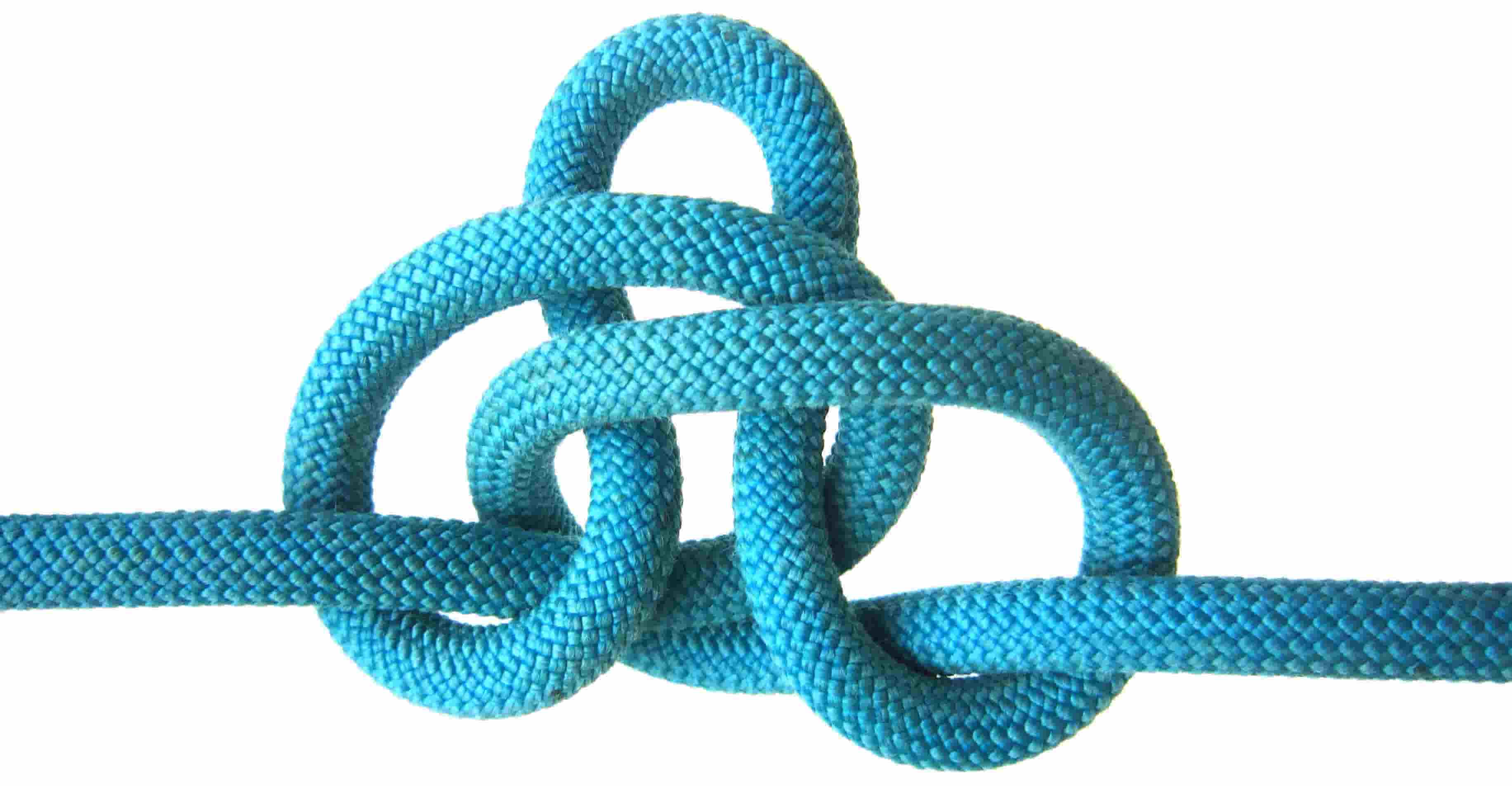
I’ve attached some real images of knots as working templates.
I’ve set the quality as best as i could with the imposed 100KB file size limit.
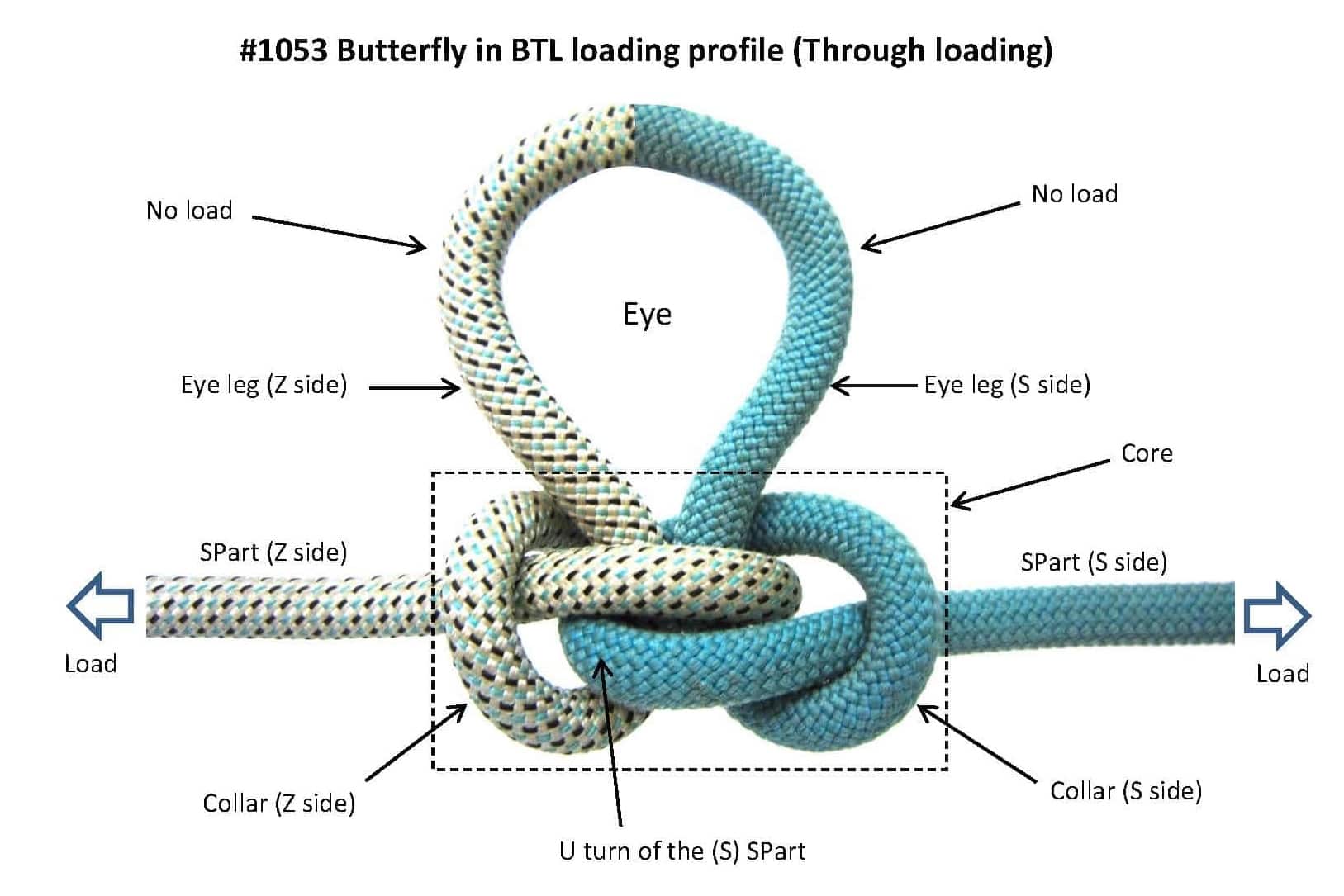
The knot is the #1053 Butterfly - and I’ve included two tone coloring to aid in understanding.
…
In a BTL loading profile (biaxial through loading) - load passes though the knot core, and the eye is isolated from load.
We can say that load enters the core biaxially - from each SPart - and the SParts are axially aligned in 180 degree opposition.
All load must reach zero within the core - no load can ‘escape’ into the legs of the eye.
Load (Z side) + Load (S side) = 0 (at equilibrium within a non accelerating reference frame).
Note: I’m not a math genius - so there could be another way to express this mathematically.
We cannot assign trig functions to any individual rope part - unless we first establish a coordinate system.
We could try to map rope parts in 2 dimensions (ie planar coordinate system).
Locally and on a small scale for isolated rope parts, this would simply working the math and avoiding spherical trigonometry.
It is false to assign the terms ‘sine’ and ‘cosine’ to individual rope parts.
We can’t do this because that is not how trig functions are used.
You must first establish a coordinate system - if planar - then simple x/y axis coordinates - with vertical y axis components and horizontal x axis components.
The sine and cosine functions are derived from the ‘unit circle’ (with a radius of 1).
We can use these trig functions to calculate force along vector components.
Intuitively, we know that force enters the knot core via each SPart.
We also know that the force must be zero at the legs of the eye.
Therefore, all of the force is captured/contained within the knot core.
We also know that a lot of heat is generated - a significant proportion of the tension force entering the knot core is converted to heat energy.
Empirically, we could load a Butterfly eye knot very close to its MBS yield point - and then loosen and untie it - and then map all of the observed stressed/damaged points to the knot structure. This would show us where the most severe forces are acting within the knot core.
We could then align these observations to a mathematical model.
Summary:
I would respectfully challenge you to apply math and to name the rope parts in a through-loaded Butterfly.
And keeping in mind that the force must = zero at the ‘eye’.
I challenge you to load a #1053 Butterfly right up to its MBS yield point - then carefully untie it and map the stressed/damaged parts back to the original tied knot (challenge accepted?).
Feel free to use my images (but of course acknowledge me as the photographer).
EDIT NOTE:
I’ve tried to improve the last (bottom) image quality…
i have kinda already done this in real word examples during working years, mostly with B’Fly as a Bend not eye tho. Loaded hard dragging sometimes even a ton or so at a time for hours or all day back and forth etc. Sometimes up hill etc. Sometimes untie several times a day as drag, take out extension, continue drag etc.
Old 1/2" arborist lines generally mixed brands degraded to dragging from overhead work, tied/bent together logs or brush piles trying to jam against anything could as dragged them. Lots of logs then parbuckled onto 20’ trailer for lumber, sometimes just minimal handling at full length. Dirty conditions, less chance of dulling saw with fewer cuts etc. Some knots were rock hard unloaded/tension captured into internal frictions. Some feel like going to burst in hand, so full of raging force, compared to the slack rope outside the knot domain inches later. Some found locked in other people’s ropes that have been there for quite some time rope jumbled into a milk crate etc. Some where to theory of isolate weak point, some where for Trucker’s type hitch pull(sometimes pulley in eye), these are most likely need to be squared to lay as if eye not used, by pulling from ends before loosening. As always i think start from end, the eye and tighten backwards to SPart when making keeps from distorting out of square most.
.
Fresh glazing and sometimes fusing/tacking of the fibers shiny apparent tho; when take time to ‘pick the lock’ rather than dispensing with ends, before another ‘butane backsplice’(ala Brion Toss) as others wanted to do. Save ropes and get some forensic data for whenever. Honestly some damage enough just cutting ends might have been easiest way as eventually seems did, but then would not get to bisect as easy etc. The main damage seemed to be to the opposing primary arcs to each side directly from the most loaded SParts. A lil’hard to tell sometimes from some stretch/recoil after loaded. This is a fair part of my hook imagery of the most loaded parts of rope are SPart and primary arc, making hook for a Hitch/termination. Opposing hooks using each other as host, for Bends, modeling from HH in right angle Hitch usage, and then HH in lengthwise usage as pre-fix to Timber etc. as then more towards a Bend function of continuation/joint than termination/hitch(define as 90vs90 arcs so not 180 but still primary/first point of using all tension for frictional seating to host. The host to the arcs was mostly softer, tension reduced tails as kinda padding, rather than the most rigid parts at direct grind as may find in more precarious Whatknot. i still like crossing tails/eye tho in B’Fly, especially in stiffer, or going to be stiffer/hard loaded rope; as seems a more Natural rope flow when let fingers ‘listen’ to rope as form architecture in it purposefully.
.
i’m no chirality (even hard for me to say!)expert; but the last pic of the 3, to my eye has (to right/blue side) “Eye leg(S side)” but in the eye half pointed to arcs opposite way to more visual Z? The primary arc just off the SPart has same design to me too/then of course mirrored to other side as printed “Z” but visual “S” to me? Thanx for offer on pic usage ; would only ask same in return myself too.
.
Going to try to say load axis/primary vs. byproduct/secondary response and leave cosine/sine(and their wave imagery) behind to go on, the math is the same as if turned the direction of force to your static cosine axis, for laws of Nature demand math same at any position, i find easier to work only on ez axis tho. We use/recognize several of what i call components as separates but sometimes not so much called in in larger knots.
The components are as mentioned, single or group of the minimal 3 elements.
Such as a Round Turn is just the 3x180 arcs, no straight parts.
Crossed Turn is Cove w/o SPart nor final nip, again the arcs not the linears
Back hand Turn tho must show SPart linear as arc taken against it.
A Sailor or sibling Pile Hitch(and associated Friction Hitches) each start with Crossed Turn component, but finish with Backhand Turn component.
loading in reverse from Backhand Turn component would weaken efficiency/more deformity in highest loaded part:SPart.
.
Been busy, no time to draw out of self at this time.
Is there particular info looking for in the B’Fly forensics?
Theory on dimensions of loaded support as applies to rope support geometry:
i think that rope force can model to pull at a 1D/linear either aligned squarely as to a Bend just as also right angle squared to a host for Hitch. 1D force for our linear 1D(imensional) force input into a node(knot in German) of disruption(from pure straight line profile) as continuation or termination of ropeForce respectively as a usual standard.
.
Then, at the very outer fringe of linear input usage/"the impossible must not be expected* " of also a 2D force possible by grabbling host at right angle Hitch/termination as above 1D architecture achieved AROUND host, but then pulling also ‘lengthwise’ in Hitch as anotherD pull ALONG host(2 directional functions 90 degrees from each other so separate dimensions) for a 2D tension/pull force architecture collectively.
Just as ABoK lends: right angle or lengthwise pulls on Hitch specifically; i think that is 1D or 2D force model in other terms, not any 3D as non-existent or forms other/external system by this definition.
i think Ashley shows/lends the proper framework, that i just name different in looking at this as dimensional geometry at roots;
but then that nomenclature aligns with concepts in bigger sea outside of knotting/languages of other (more evolved/broader examples)disciplines/raw mechanics, for more definition(s) and cross-verifications.
.
i look at this as must show 1 dimension, to then reach for the next, and the root is the benchmark cosine 1D linear. this gives layers of complexity: Simple, Compound, Complex for 1D, 2D, 3D respectively.
Model rope as simple loading rigidity w/compound considerations/deflections on that scale, but not as fully complex as rigid potentials by comparison.
.
Can show this 3D of concerns with just cosine and sine tools as the Ancients lend, to cover all (even potential) connections in a model,
of simply a linear initiating force like gravity as cosine and all 90 degree deflections from as sine to cover all incidences in a connected model.
You can align model to standard cosine benchmark to show this/ showing strings of offsets from benchmark for the each step/calc or take cosine and turn so aligns with 1D force to simplify/minimize math operations as use cosine as a ruler/protractor instead to the model (whichever is lighter to you, moving benchmark to suit kinda makes the mountain come to Mohamed for me) to get same answer of course.
.
Whether that model is to show displacement against space(distance) or it’s reciprocal displacement against force;
model would simply include all, purely aligned properly or not of all possible connections/potentials, as then also gives the ratios of change/percentages of whole for aligned and deflected parts each. Really, cos/sin quite a gift to us across time, that covers all so well, so deeply!
.
Rope works rigidly against a linear force that can be shown most simply as cosine1D aligned along rope’s length (aligned 1D functions)in tension(using protractor turned correctly on model) , external side forces(to that ropePart) can deflect some into sine2D from the rigid cosine1D benchmark 1D line.
In rigids, the sine2D itself would be rigid, and could plot 90degrees to another dimension that was not cosine for then achieving a 3Dsine model.
However, rope as a flexible, by definition cannot be rigid on the cross axis to even sine2D to then show a force deflection into sine3D.
So ABoK just showed the 2 dimensions of Hitches, right angle 1D and lengthwise 2D, as complete; i believe correctly so.
.
A rigid device has the capacity to resist internally against on it’s sine2D cross axis to at least foster a sine3D force deflection from this rigidity, and then would also expect a further rigidity on the sine3D axis(but can construct where resists on 1 cross axis sine2D and not other axis sine3D).
Rope/flexibles class simply has no such capacity by definition. Cross axis resistance in rope/flexibles has to come from external, not internal influences, so can’t show a sine3D rigidity, nor foster a deflection into sine3D from a non-rigid 2D aspect all starting from benchmark cosine1D loaded rigid theory.
(axes is the most correct plural of axis, except for tree guys!)
very 1st lines of opening pre-ramble of ABoK chapter_22 exclusive chapter on single topic of ‘lengthwise pulls’, that i frame as 2D:
“To withstand a lengthwise pull without slipping is about the most that can be asked of a hitch.
Great care must be exercised in tying the following series of knots, and the impossible must not be expected,
particularly on a wet and varnished spar, or on a polished brass fireman’s pole.”
which then later suggests prepping the surface with tacky stage of varnish, wood ashes or even best slit open rubber innertube to increase chance of chosen knot grip at this “treacherous”(ABoK) ANGLE of pull; and notes to expect this to be directional/work 1way on this “lengthwise” axis(all tho we do find some to be bi-directional along the lengthwise axis of host.
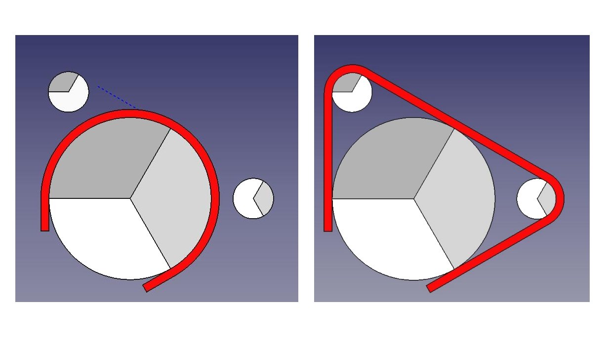
Is it right to see this whole-half-arc vs. piecemeal
x 4 as indicating why in the latter case there might
be sufficient friction to turn the --what I’ll see as a…-- wheel,
but where each of the 4 wheels has only the lesser contact
then there cordage would slip w/o rotating them?!
1st would say believe in the half circle arc180 area of contact view pictured,
and use Dead-Eye(non-rolling eye used as pulley?) as ABoK imagery reference item for them.
Bulls-Eye hitchpoints as earlier predecessor,
Ashley says from Egyptian times, one in short piece of rope was called a ‘lizard’ have read.
.
This imagery shown by Structor is something that i personally don’t see so well in this case;
BECAUSE no top combined apex , 2x downward force just separate 90’s of across force at that KEY/ most responding apex SUMNATION position(but book says Structor is right).
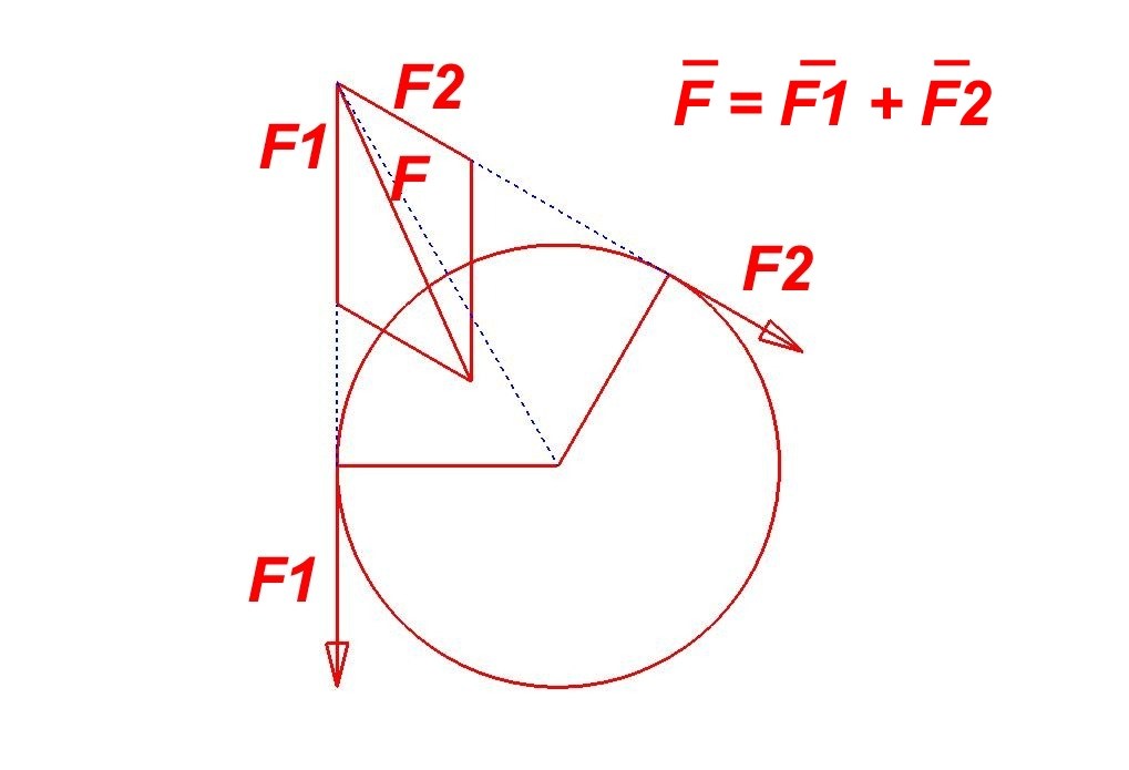
i look at the apex of an arc as most responding point of arc flow, expressing more force against host than carried internally at same point.
To me, arc90 @ apex45 potential force= [.707(cos)+.707(sin)] X tension=1.414 X tension contact force against host(usable for controls of frictions, nips and grips). * As most potent controlling force to rope.
.
While, arc180 apex is the back to back 90s of now 2cosines of 1ea. at top apex, 2x where there was no downward force into host before with a single or paired 90’s! A 180 is a unique structure in that both ends and then even middle work the same direction and so then does the whole form in any material.
For the best nip is at that same 2xTension pulley position(as both expressions of this arc180 geometry), from the 2xCosines of the back to back 90’s.
To me, that would give more surface contact pressure/friction at that point and still have
1.414 X tension at each 45degree deflection from apex also(??) So to me, a top center arc giving more ‘pyramid’ look, to collect/capitalize on the 2x downward pressure that appears.
i tried to show this theory previously in this drawing :
It seems only logical to me that the frictions would come from the forces seating rope to host.
.
BUT, Structor is correct to collectively show these combination of the degrees to same frictions as a single contact per
http://The Mechanics of Friction in Rope Rescue -Stephen W. Attaway, Ph.D.
and as we see in rappel rack.
So i go along with the paper(and Structor), trying to see where it points as it has confirmed and lit so much for me in points and connection of those points to contiguous fabric of understanding.
.
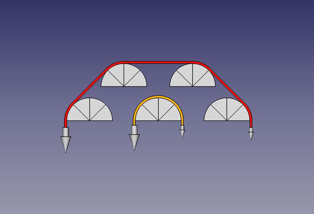
From there, the piecemeal as a system also works to break up(like rack)/not concentrate(like bollard)heat from frictions, gives rope a thermal rest between ‘cooks’ somewhat i think.
But, yes full arc180 at once has more frictions to grab on a single wheel/sheave to be able to turn it, where the piecemeals may slide on lower 2 or all and not have enough to turn wheel/arc disposition from whatever frictions surface or axial. The full arc180 has some actual grab to host of opposing forces on both sides of host that drawing proposes not to use. Drawing has 1 sided single pulls, not grip from both sides on any single arc shown in red rope trace (that is in yellow rope trace).
.
*
Straight faces on host into that apex, give only the apex as full tension forces, but arc faces on either side of most responding apex the apex and the Natural flow of the arcs all get full tensions, as a running deformation from inline, not just the apex as in a squared corner.
Just one example of how important round host is, that lends that shape to rope architecture, to then work more against host if Natural flowing/rounded/arched not sudden jarring linear/cornered changes of direction given to loaded rope.
This post isn’t about knots directly, but rather how all things, can be decoded down to cos/sine (alignment/deflection displacements), even rope/knots. Raw knot elements(arc0, arc90,arc180), can’t be appreciated as well without this view to see how pivotal they are; to then fold into more recognizable components(Round Turn, Crossed Turn, Backhand Turn etc.)
.
Cos/Sine can describe ANY physical(keyword) displacement(keyword) against(keyword) space(distance) or force
force as the traded reciprocal to displace against space/distance, so implied whenever speak of change in distance.
this even defines movements of whole galaxies.
The Ancients used the whole heavens watched for a whole year as like microscope to see what was happening in own hand in a moment.
and handed this heritage down.
.
This view here is more to a waveform view of cos/sine initiated by a linear force line, here shown as vertical/horizontal models as one.
.
As stepson went to engineering school on up thru master’s and bits beyond;
most of what i sent to find at school on these topics where to confirm, or get proper term for comparison and research, true senses to, where to take chase next etc. of bits and pieces kinda grasping as danced just out of reach.
But the principles below really helped as a real jewel of many facets, that really turned on the lights in dark corners and powered many palm slaps to forehead was different. And very good benchmark to judge/light to read other things by over time.
Some of the verbiage of extreme to either side of Natural/resting state/self equilibrium(cos1 ) at cos0, breathless stall then overall relation to stroke and cycle, thru recoil phase and carried inertia phase;
i dressed in from other things >>after he confirmed piston vertical sweep center of run =cos1.
See high/low extremes as cos0 @ breathless stall before reverse to other cos0 extreme etc.
but passing thru Natural state of cos1 to do so
.
In waveforms (light, electric, sound, water, wind etc.) the cosine wave pulse from forces is seen first, then 1/2 stroke(1/4 cycle) later (@90 degrees) the sinewave is shown. The initial force pulse(regardless of duration) is the cosine wave, sine as a later byproduct. Thus shows across thru the models i present as 1 consistent , not segmented theory; binding a force pulse wave across all force models.
Perhaps seen before in foraging, not even sure because seems could have easily glazed over w/o him stepping me thru.
So put this together from both ideals as one to the defining commonalities and language of 1 lesson.
Above was to show how the very simplest mechanix can be broken down to cos/sine.
.
More on LINEAR vs. RADIAL usable forces for frictions in Radial, just as greater support in arc/Radial support than in Linear bridge.:
Simpler, Linear expressions of friction (and support) can’t use cos+sine as 1 sum to a single purpose like friction, support etc.
here cos is used for direction of movement maths, and 90 degrees later sine to surface/friction contact maths SEPARATELY.
1 element runs across linear path(direction), the other into the path(friction)
if travel is into linear form, that is collision, not friction, that would be at the 90degrees to the sides as collision went thru
Very simple, as expected scalar/evenly graduated maths of progressive changes/increases
CoF(CoEfficient of Friction) for the mated materials X distance X weight = Frictions, Efforts needed.
.
More complex, Radial expressions of friction (and support) can use cos+sine as 1 sum to a single purpose like friction, support etc.
here cos is used for direction of movement maths, and 90 degrees later sine to surface/friction contact maths COMBINED!!
Both elements direction and byproduct run into/around radial !!
if travel is into linear form, that is collision, not friction, but in radial that flows around and becomes part of the support and frictions!!
This is then COMPOUNDED EXPONENTIALLY and by degrees not distance (180 degree units as a ‘stroke’ ) !!
Example shows when give 3x arc180s can return 12.5x more friction than a linear/scalar math of 3xDistance giving 3xEffort needed.
This is how stuff works..
These forces command the rope elements of arc0(linear), arc90, arc180;
that are the raw elements of recognized components of (simple, single)Turn vs. Round Turn; nip points, grip architectures , frictionals etc. and if these are compound expressions of radial or more scalar linear in the assertions with the carried forces thru the rope pipeline.
Focusing on RADIAL frictions as a key changer of Tension down length of line to want to pull out less
as also makes the rope softer across the length of the line to give way more, at some point soft enough to nip.
.
Examples for me of workings inside a knot microcosm is easier seen externally in magnified view as a singular specialized topic.
Radial Friction examples outside of a knot in magnified view, expressed ‘loud’ enough for us to hear are best shown in a radial list of arc180s around a ropeBrake/pipe type device, or a linear list of arc180s on a rack.
Will find the same geometries, set to different CoFs working silently, unobserved inside of knots .
Rope Brake, capstan, bollard, Porty etc. RADIAL frictions in tree work , also show same math, to less extent in knots. Roo’s NotableKnotIndexpages talk some about friction.
Offers a picture showing 6x arc180 with rope to metal CoF of .3
input a HOLD(not trying to lift )of 7# effort LEVERAGES to holding 2000# monster force (by comparison)at bay with this ‘simple’ math. http://Notable Knot Index: The Power of Friction
My version way back when was drawing of a baby sitting on the end of a rope going to tree warps, holding back a bus!
. Notable Knot Index: Pipe Wrench from Rope shows an interesting old-timey usage of this ever present force to harvest to such services.
and also lists this Google Calculator readout showing the formula again , and the keys used for E, PI, exponential etc. to the 1ton sum of hold from the 7# effort!
7x(e^(0.3 x 6 x PI)= ~2000# is all it takes to peel back the curtain and peek at the wizard workings hidden in microcosm of a knot.
so how to command this and other things around you; with these ‘simple’ mechanical commands, as like computer commands.
.
As friction reduces the tension of the rope, it also reduces the rigidity, to a more ‘nippable soft’
.
line_14 of spreadcheat below reads: ‘triple round’, 1080 degrees , 6x arc180 0.3 CoF gives 285.68 friction factor leverage in chart
7# holding effort X 285.68 leverage = 1,999.76# force/load held
wish had such an easy 285x lifting lever, but 285x easy brake leverage is nice to know too !
Nylon on ropeBrake of Aluminum vs Steel also shown for how much difference change of CoF and turns matter exponentially in this organic pattern
By the engineering numbers, a nylon rope on an Aluminum vs. Steel round ropeBrake device;
gives exponentially wider and wider frictional differences with successive arc180 turns.
The only variant is CoF Nylon w/Aluminum @ .25 vs. w/steel @ .40
Stuff like this can be much more of a mystery until can pull the curtain back with the numbers;
and start to read as like on the right frequency, with less garbled dead spots etc. in what you do get.
Always tell self more of an open the door, rather than peek underneath the door; look at the world.
The math says this is a lesson in all things.
.
Working with a capstan/bollard/ropeBrake allowed me to understand frictions hidden inside a knot microcosm much more fluently.