physics of a riding turn

For some reason, I am stuck trying to mathematically solve the physics of a riding turn. The calculus of the capstan is pretty simple, but I must be making some mistake trying to come up with the compressive force at the riding turn. Ignoring friction of a rope on itself, the rope should be at maximal tension without slippage when the frictional force equals the hold force of a 360 degree turn. Since the capstan equation is T_load = T_holde^(frictional forceangle of rotation), the frictional force (Normalfrictional_coefficient) should be equal to the hold force to prevent slippage. How would this be described mathematically? Essentially, what is the compressive force at this point? Mathematically, the Normal force should be equal to T_load/(frictional_coefficiente^frictional_coefficient*angle). At equilibrium, what would this be?

Edit, thinking about it, I expect T load would be equal to frictional force (which is the coefficient of frictionnormal) for the loop of suture, since there is no movement. The hold force would not change based on the number of wraps, as it is just the tension needed to prevent slippage of the suture. So mu times normal = T_hold x e^(mutheta). The normal force would be equal to (T_holde^(mu times theta))/mu. So the normal force is proportional to e^(mutheta). Doubling the wrap would increase the normal force by e^(mutheta). One turn is 2 pi radians, so the increase would be e^2pimu. (I had initially said by e, but I forgot that theta’s units should be radians, not revolutions, and forgot the mu).

The importance would be that a clove hutch has two wraps in the same direction whereas the cow hitch has two turns in opposite directions. One would expect that the clove hitch would be tighter.
The Clove hitch should be a good candidate to apply your theory.
Although the orientation of the Clove hitch would alter the effectiveness of the riding turn.

Attached image illustrates 2 typical ways of orienting the Clove hitch.

The first example would have very different physics. The capstan equation itself depends on several assumptions, which may not be relevant to a particular knot. The cow hitch actually has some features that weaken the grip, such as the tight turn in the middle that would poorly constrict with stiff suture. My interest lies in gripping power of various nooses. Maintaining tension is commonly taught but a bad idea in surgery. Imagine tying off a piece of wet tissue paper. Tension avulses vessels, saws through tissue, and contributes to inadvertent nooses. In addition, it leads to premature locking, or air knots. This latter effect is due to the kinking and resistance to sliding when there is tension on both ends. I have a diagram that shows this, but it is easy to show with a piece of cord.

Trying to get real numbers, I think the coefficient of friction of uncoated plastic type materials on itself is 0.1 to 0.2. https://www.engineeringtoolbox.com/friction-coefficients-d_778.html
Going from one turn to two increases friction from 1.9 to 3.5 is the coefficient is 0.1. (It would increase from 3.5 to 12 if the coefficient is 0.2). So one would expect the increase in friction would be at least 80%.

I think Crossing Turn over emphasizes frictions of underlying turns/ pasting them firmer at that point, as firmer heat or electric transfers more force, which reduces more tension flow past this point in hitches and bends etc. Radial position from SPart of crossing determines how pasting tighter exaggerates frictions at that point, but full circle evener load linear friction around. Binding is different as more even tension around force from inside binding serving out.
.
I’d think would go more frictive line perhaps in linear arcs run like Surgeons employs give more linear frictions on binder it self perhaps crossing to firm same against host vessel might be fair direction, but can’t really imagine this tying fishline with tweezers within a thimble around a damaged wet noodle w/o tearing it as try to bind strong with child’s life hanging in balance if do right, while racing the clock etc.!

Capstan doc shows half arc builds at right angle around host, but also linear

Kind of late and I’m not sure if this is of help, but it may be a little more complicated: I think that tension changes around the capstan and so does the normal that determines friction at a point around a wrap. The ‘capstan equation’ integrates the changing friction force (due to changing Tension and thus changing Normal) around the capstan wraps. Try this one:

https://ocw.mit.edu/courses/physics/8-01sc-classical-mechanics-fall-2016/readings/MIT8_01F16_example8.11.pdf

i’m great fan of capstan equation and insight it brings:
jrre.org/att_frict.pdf (link working again)
Also: Flat and Radial CoF Spreadsheet.
.
But, i think that suture would be a Binding Knot type usage
Binding Knots are totally different class and chase to me of an equal radial not decreasing linear force thru rope;
thereby again; i don’t think of as part of capstan pull or brake force scenarios etc.; as has different power source and pathing to the locking etc.

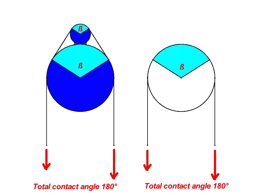
Similar cases of rope contact.
Total contact angle 180?.


angle.jpg

per KC:

Binding Knots are totally different class and chase to me of an equal radial not decreasing linear force thru rope; thereby again; i don't think of as part of capstan pull or brake force scenarios etc.; as has different power source and pathing to the locking etc

A binding hitch will have force injected at both SParts simultaneously - and those SParts are typically axially aligned 180 degrees in opposition.
The capstan effect is indeed playing a role, and so are any ‘riding turns’ within the structure.

The ‘power source’ you allude to is simply the human hand pulling and injecting a tension force at each opposite end.

If there were no ‘riding turns’, the binder hitch would not be able to progressively increase the tension force.
For example, in a #2047 tensionless hitch, there are no riding turns - and also, force is only injected at one SPart (there is only one SPart, not two).

A classic example of a binder hitch is #1188 Constrictor hitch.

#1188 Constrictor hitch has 2 SParts, with force being injected simultaneously at both ends (which are axially aligned).

The so-called ‘riding turns’ act as a ‘progress capture’ mechanism.

This is the key to how a binder hitch works - in that as the tension force is increased, it is progressively ‘captured’ by the ‘riding turns’ (or a similar geometry involving one rope segment crossing/contacting over another).
I would also comment that #1188 Constrictor hitch requires a ‘host’ object to form around (as do all hitches).

An interesting progress capture mechanism also exists in the ‘Poldo tackle’ which is illustrated in ‘ABoK’.
See this link for an interesting discussion: https://igkt.net/sm/index.php?topic=5377.0

Struktor very nice question and by the numbers YES.
Am at work, can’t play with the math etc.;
but essentially my take-away on this is the eye lies when it says these are different, that the force is by degree not distance of contact per same load and CoF mating pair.

side note in belt drives to get 1/2 wrap friction on smaller pulley has to be spaced out of this ‘eclipse distance’
att_frict does say essentially your pic is correct (if rock solid), paper shows collective arcs calculated as total amount of degrees added together as one in fig.8 and rapell rack then later over succession of rock face lips rope traces over and each lip is calcd to output force and new formulae from output tension of previous; but in the Euler Natural growth progression math, this should be about all the same as when all added together to calc; just like if calc compound interest for yr or month to month; as is based on same type formulae (which itself almost matches what is called the most beautiful formulae in math!).
This is all counter-intuitive, but i believe that is the point of the paper, to retrain what eye sees or interrupt what it says to brain..
(In all fairness; at one point about this says needs more definitive testing, but this is base answer still standing in 20yr old doc.)
.
agent_smith comments:
When we set Binding Knot is as stated you pull the SParts drawing away from each other . So Clove not Cow family as base preferred, and not so much Groundline as has the mechanix of trap like sister Bag Knot, close to Constrictor; but not the opposing draw positions so much for setting the trapping mechanism.
.
And at this point that is what we are talking about is setting knot like mess with Working and Bitter End(s) before loading SPart of Hitch or Bend usage unloaded.
But, in actual loaded usage phase, set load from SPart in Hitch or Bend, but release what were SParts in Binding and they become the Bitter Ends as the force now comes from inside the turns thru evenly sourced from compression binding host uniformly around, best if imagined or have springy host like compressing bag closed rather than solid/just stand ground of spar response to binding . Pressures divided by turns now, receding thru locks of crossings to Zer0 tension of Bitter Ends that started out as the setting pull points as SParts.
.
So, like compressing spring in pre-usage is down, but actual usage of spring inverts to relying on it returning favor and pressing up against bounds of given capture. In each case after setting hard and release as a free agent, the force flow direction reverses in the same wired machine for different effects. This is power source i refer to, the pressure in of binds against host during usage, were ends are Bitter Ends, even tho in setting as you show the same are SParts. Inflate host of Hitch and performs support job no better, inflate host of Binding and it does do it’s main job better.
.
Binding Knots are totally different class and chase to me
Hitch usage is a linear force thru rope to a termination
Bend usage is a linear pass-thru /not termination
But in both the greatest force is at one point as SPart feeds force in that gets reduced at first arc, all further points are lesser to Bitter End
i think this is more of what capstan equation is about a linear feed force at peak point, then reducing around as formed into radial pattern, not so much radial force source evenly around as force source and flow pattern.
.
Binding Knots are immediately different in 2 ways:
radial, not linear force (opposite geometric)
force from the inside of knot and back in type fight with internal host not external load
thus radial force powered lock of Square (Binding )Knot minimalist form works, but not linear lock powered as Square Bend fails.
Bag Knot(a general fave) on small host mount as Hitch, places crossing higher around radius to better Nip than Constrictor(perhaps), but Constrictor more re-enforced thicker wall against even expansion from inside
In more common Hitch termination or Bend pass-thru the linear force lessens thru line in arc(s)
Binding presses in evenly around as host presses back(better if host trying to expand outward rather on static log i think) catches a crossing to lock.
So more even rope tension around until the crossings
not so much capstan of power or brake to leg(s) outside of turns that feed to control linear SParts outside of knot; that in binding are now Zero, not full bull at end(s) as loaded in Hitch or Bend.
So see pulling as taking a purchase that system holds fast to me.
.
Gotta run (y’all saved by the bell!)
But in suture bind of damaged wet noodle/firehose, position of crossings should be at strongest , most elastic, convex responding portion of host mount/noodle to secure, as perhaps more important than extra tuck random , perhaps of lesser position of soft, flat, concave, bumpy, less elastic, less round etc… All locks are host dependant (even if back to rope itself), but no tension decrease before lock in Binding usage, so host more important as locking mechanism fights more full force of Binding, than reduced forces of Hitch or Bend affords more so.

KC:

Being a native English speaker, I have to admit that I am struggling with your narrative.

For example:

... So, like compressing spring in pre-usage is down, but actual usage of spring inverts to relying on it returning favor and pressing up against bounds of given capture. In each case after setting hard and release as a free agent, the force flow direction reverses in the same wired machine for different effects.

You are introducing a spring as an analogy but, your sentence structure makes interpretation rather difficult.
Springs can in fact be tension or compression type.
If you meant ‘tension spring’ - I am not convinced that this is a correct analogy.
If you meant ‘compression spring’ - in “pre-usage”, there is no net force acting. You have to apply a force to compress the spring, and then it resists and tries to return to its initial rest state.
Be that as it may, in broad terms, I understand what you are trying to explain with this analogy.

and this…

Binding Knots are totally different class and chase to me >>Hitch usage is a linear force thru rope to a termination >>Bend usage is a linear pass-thru /not termination
Okay - in both a 'bend' and a 'binder hitch', injection of force is via both SParts (standing parts) which are in axial alignment, but 180 degrees in opposition.

However, a ‘bend’ requires no ‘host’ object. In contrast, a binder hitch does require a host object.
In a ‘bend’, there is a collision of force at the core - which undergoes compression. During compression, some of the ‘energy’ is converted to heat (we can see this with an infrared detector).
Bends can be either symmetric or asymmetric.
In the case of a Zeppelin bend (which is symmetric) - the core resists compression due to a toggle mechanism created by both tails.
I can understand what you meant by bend “usage being linear pass-through, not termination”. However, due to core compression, friction, and conversion to heat energy, the ‘pass-through’ of force is not 100%. But, I get what you are trying to describe (its a ‘through loading’, from Spart to SPart).

As you pointed out, a binder hitch can be tied around a solid, non-deforming host or a crushable (deforming) host. And here you stated that force “terminates” - presumably you meant it terminates by crushing the host object. However, a non-deformable host would present different parameters.

and this:

But in suture bind of damaged wet noodle/firehose, position of crossings should be at strongest , most elastic, convex responding portion of host mount/noodle to secure, as perhaps more important than extra tuck random , perhaps of lesser position of soft, flat, concave, bumpy, less elastic, less round etc... All locks are host dependant (even if back to rope itself), but no tension decrease before lock in Binding usage, so host more important as locking mechanism fights more full force of Binding, than reduced forces of Hitch or Bend affords more so.

Its tedious to read and try to make sense out of what you have typed.
You introduce terms such as ‘suture bind’ and ‘wet noodle’ without context.
The “extra tuck random” and “locks are host dependant” seem nebulous because there is no reference frame from which to glean a meaningful understanding. The last sentence is just too tedious for me to unravel and extract a meaning (sorry).

If English is not your first language, maybe try breaking up your paragraphs into clear sentences which deal with just one concept at a time?

My apologies , I have always had problems with this, simply think different. This is main reason play with drawings.
.
My total imagery of binding is different than what you are looking at.
To me , you are looking at setting phase; I’m looking at after released as working phase

where ends are BE vs. Your SPart view of them. i’d try to segment frictions and not pull against all at first, but have tails/BE laced and ready to backup initial setting to lock. Then, I see binding pressing in and host responding back. So, radial force to me, but that is ignoring work of purchase in setting phase you see/focus on.
.
To me, an arc (not in air as a bight) rides a host mount. Be it a load, support, other rope part, etc. generically rope rides around host mount.
.
In electric schematic type breakdown :

https://upload.wikimedia.org/wikipedia/commons/e/e5/Some-schematic-symbols-rope.png

Also pulley set as transformer, 1way tended prussic as diode, friction as resistor etc.

From start Isleofgough has posed knot reflections of surgery, suture etc. in relation to binding. Picturing somehow vessel tying as wet noodle that can fill, flex, heal, go soft etc. as unusual complications and gravity, especially racing the clock tying fish line around wet noodle/vessel with tweezers inside of a thimble.
.
And to original query, again say the crossing turn effect depends on tension and reductions from capstan math, AND radial position just like low, mid or top nip of crossing greater over lesser. This is viewable in Clove side crossing vs. Sailor top crossing, and if Sailor cross on side, not shifted to top is totally different if Sailor proper top crossing, rest of knot can go about limp compared to side crossing.
.
But those are linear degrading force around, not what I see as radial glow evenly of force outward as bindings collectively matched evenly around. Capstan math not full story to crossing frictions for hitch and bend, and not sure counts in ‘holding purchase fast’ phase of binding.

per KC:

My total imagery of binding is different than what you are looking at.
Correction... I'm not looking at anything. I am merely stating what is obvious.
To me , you are looking at setting phase; I'm looking at after released as working phase >>where ends are BE vs. Your SPart view of them.
No, I'm not.

I’m simply pointing out that I am struggling with your narrative.
Your sentence and paragraph structure make it difficult to extract a meaningful understanding.

Be that as it may, I can see that you are passionate…and that’s a good thing.

Thanx.
.
To the original question:
Crossing Turn pressure in Hitch and Bend i think is by radial position as in the reverse of lesser tension Working End(WE) burrowing under (not over) greater tension part more of Nipping.
.
Crossed Turn (lesser tension over greater) reverse of Nip(greater tension over lesser):

https://upload.wikimedia.org/wikipedia/commons/c/cf/Nip-crossing-vs-crossing-turn-sm.png

.
But, both of the lesser tension WE crossing over or under the greater tension existing turn;

show more effective pressure on top/side of host mount Equal and Opposite from the initiating load pull side as force source .:

https://upload.wikimedia.org/wikipedia/commons/f/fc/Sailor-hitch-side-vs-top-crossing-pressure-change-by-position-like-nipping.png

.
But, maintain even that changes as go into radial force of Binding.
.
edit>>also note that prized top crossing position would be less deforming to IBeam of support to Load:SPart for more retained efficiency/strength.
vs. side crossing that gives more deformation, vs. (then in succession loser) most deformed of Bottom Crossing (off host support backing) directly across IBeam of support to load:SPart.
Sailor is very unique hitch, as sisters Pile/Icicle of same hybrid family of combining crossed turn on host and off host Muenter (Spart thru crossing type of Backhand Turn like Cow/ both ends thru crossing)into 1 lacing. As Sailor, would always load Pile/Icicle from the Crossed Turn side, not the Backhand Turn side, for less pressure against SPart.

Many of you may have heard about this paper, but it gives a lot of insight on knot security by looking at topology using color changing photonics fibers: “topological mechanics of knots and tangles” P Vishal et al, Science 3 Jan 2020 vol 367(6473) 71-76.

Per struktor’s interesting observation above . . .

Defining an angle, θ, relative to the origin and vertical axis of the larger radius as seen in my first attachment, the tension in the rope as a function of theta is shown in my second attachment. The tension in the rope with and without a riding turn is shown and a line to guide the eye. The ratio of the radii is 3:1 with a coefficient of friction of 0.2.

i think that just as there are stronger Nip positions by radial position of towards load, side or opposite side of host than load
(Ashley’s 3 Half Hitches of basic, fig8 and top nip)
give the same pattern of changing intensity as intensities of change per ‘frapping’/crossing/riding turn by position of application

that the riding turn crossing just emphasizes pressures against host at that position, per the radial position from source input directional axis
unless changes to the cross axis with a 90degree rope arc
otherwise expect arcs central compounding point to express in vertical axis if vertically imposed (like gravity powered load)
.
From more pivotal/deeper cosine view:
i view cosine as the raw axis of load force , the rawest, strongest, most intense axis confined to that single dimension with load
where the focused, linear force is most pure
sine is the spray to the sides of deflected force, not raw in this model
The intensity of how the remaining/persisting rope tensions at a given point around host are ‘expressed’/used against host
is most intense on the cosine axis , not the deflected to sine axis
Even tho by my definition, the arc uses all tensions for frictions, just as stone arc uses all load in compression
so that uses tension x cosine + tension x sine (thus all) and sine increases as cosine decreases
the cosine is rawer, not deflected and so the most intense usage/expression remains on that cosine axis
This gives the ‘compounding point’ of 2/1 potential in pulley, greatest seating to host and in any crossings
greater over lesser more nip expressed by more raw cosine position than reversed sine and cosine values (so would think to same sum)
even if closer to SPart as original force source/input imposed
with more added frictions but better radial POSITION>>greater effect of crossing lesser force Working End(WE) over greater force already existing turn( closer/less frictions to SPart as source) to further reduce beyond nominal frictions the force persisting thru that point
or even WE as lesser force crossing under existing greater force turn as to try to Nip.
i call this radial dominance or radial apex dominance
and find simply that the 2/1 factor and position of a pulley is the compound point of the arc
and in knot this compound point is greatest increase in nip or crossing position forces.
and then by same maths >> the best crossing position for greatest effect/least persisting original force remaining after

.
So that the crossing/riding/frapping turn in a Clove, is less intense at the side very close to source input with very little frictions between;

than the top crossing/frapping/riding turn at the top of a Sailor’s Hitch
even with more previous frictions between that position and the same source load in Sailor’s vs. Clove
so less tensions running thru that part of rope in Sailor’s crossing top point
but more intense nip and crossing changes persists >>even from less tensions after greater collective frictions!
as the directionality of the original source load imposed as input counterintuitively persists thru the turns
but only if from focused linear input converted to arc control
NOT if radial source of force from Binding usage, even in same knot, such as SAME Constrictor (or Bag, Groundline etc.) used as Hitch or Bind
because the source force type is different>>the linear is focused and thus directional vs. dispersed w/o direction radial
The focused directional axis persists thru the turns
when the source force is linear pull of Hitch or Bend onto SPart>> then converted to controlling arcs
but, not in Binding where the source force input to same arcs is radial dispersion w/o focused direction by contrast
Axis and direction are VERY important values in support, especially of linear/non-raidal force
.
Sailor’s Hitch is a very special model, extreme in this fashion and others.
it not only has a turn crossing another, but they both also sit on top of the Bitter End!
it squares forces to this position with branches of an X to either side as Constrictor and Bag do
it is a compound build of a Clove like crossing turn (but rotated to top) and a Backhand Turn like a Cow
but the Cow like turn around SPart deforms it very little if loaded from proper end where the Clove type crossing is encountered first
when this crossing is at top region, most opposing a gravity load very little force trails out after
so not much left later to deform SPart with the Cow type Backhand Turn.
If we rotate the crossing in Sailor’s Hitch to side where i show SPart ends, to make more like Clove
there is now more pressure left over to press against SPart to lower strength efficiency etc.
Rotate crossing back to top and the knot switches gears, to very little tension left after the crossing
premium example of greater crossing pressure, at a position with more frictions/less remaining force

More fascination w/Sailor’s Hitch:
In lesson#1209 Ashley seems to chuckle:
" The LIGATURE KNOT is commonly called by laymen the SURGEON’S KNOT. But surgeons do not speak of the “SURGEON’S KNOT” any more than a sailor would speak of a “SAILOR’S KNOT.”
Then, doesn’t name knot in lesson#465(top crossing) and #1693(side crossing) that we call Sailor’s..
Lesson #465 notes: “To make fast a swing: The accompanying hitch is recommended, as it stays in place and does not chafe against the crossbar or limb.”
i think this doesn’t give sawing action on limb, as the force flow is so completely cut off at top region crossing, that just pivots from there more than completes across to sawing motion or rocking/swing

The crossing shows at top region slanted to opposing side of SPart, this would make it at top at swing away to SPart side, the most critical leveraged angle of moving force test of the lacing in this usage..
Round is very important in knotting and other rope mechanics
Sailor Hitch ‘poofs’/serves the crossing up higher with Bitter End as trestle as Ashley also shows in slips w/lesson #1708:
“The loop of the SLIPPED HALF HITCH bulks larger than the single end of 'N 1707; for that reason it is perhaps a better hitch.”
giving exaggerated roundness at that point
so even as is getting super top nip, from 2 ropeParts, braced on sides so can’t escape that focus
barely any force makes it that far in top region nip
as the top nip, especially with exaggerated roundness about clamps shut on the ‘garden hose’ to turn off the force flow thru.
These parts of ropeMechanics is why i call these lessons and look for the mechanix to cross compare in other things, and to carry to yet other’s lacking their attributes
In this way i find a very consistent theme across much of this
that in review is not an isolated island of principles particular to rope or this knot
but rather a larger engulfing sea of same principle all around an item in larger mechanics shared by everything.
This gives cross verifications and different aspect view of the same gem, to fold back to original topic with deeper understanding
and confidence , and urgency to learn, for now see get so much more out of it than before,
for same lessons now cover many more things, and have fuller view!

Interesting challenge, stepping into the realm of positive feedback.

Using the diagrams provided by MMC,

https://igkt.net/sm/index.php?action=dlattach;topic=6574.0;attach=26504;image

Assuming the red line is the riding cord and the small top circle is the ridden cord, I presume you are attempting to compute the normal (i.e clamping) force of the small circle against whatever is below it.

MMc’s diagram allows you to make an estimate of the tangential angle of the overriding cord and his second diagram allows you to compute an estimate of the tensions either side of the overriding contact

https://igkt.net/sm/index.php?action=dlattach;topic=6574.0;attach=26506;image

Using the parallelogram of forces you can then compute the diagonal which is the normal force using
c^2=a^2+b^2−2abcos(C)
where c is the diagonal and C is the included angle.

You can estimate the area of contact of the ridden cord and knowing its cf and the normal force, you can compute the load needed to move it against friction.

A little more about what you are trying to achieve would be very much appreciated.

Derek