Re: Three collar V. (virtual) bowlines or munter based bowlines

                                                                               [u]Advantages[/u]
  1. There are three collars, one that encircles the on-going eye leg (in other words, a crossing knot is an individual component of the nipping structure), the conventional bowline collar, and finally the collar that clamps both collar legs at the second stage (near the eye). Now, bending the collars in the order they were mentioned, you are able to untie the knot without jamming issues, after heavy loading.

  2. There are two direct lines of defence against slippage.

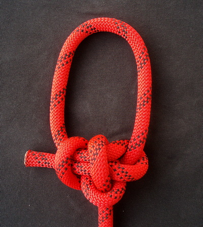
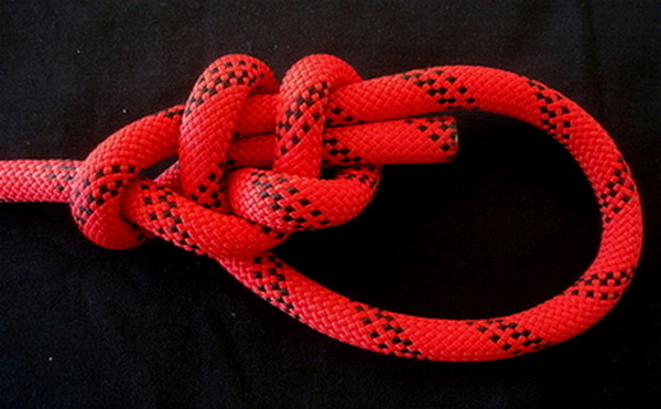
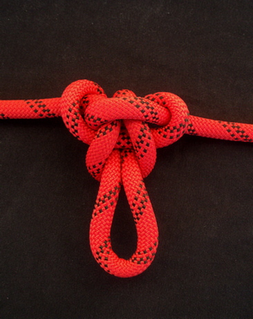
  3. The TIB nipping structure, allows the formation of a TIB instance, if the WE is tucked back through the collar (fourth image).

  4. The EEL property is in force, with the feasibility to create a reverse crossing knot based profile (which will follow in a subsequent reply).

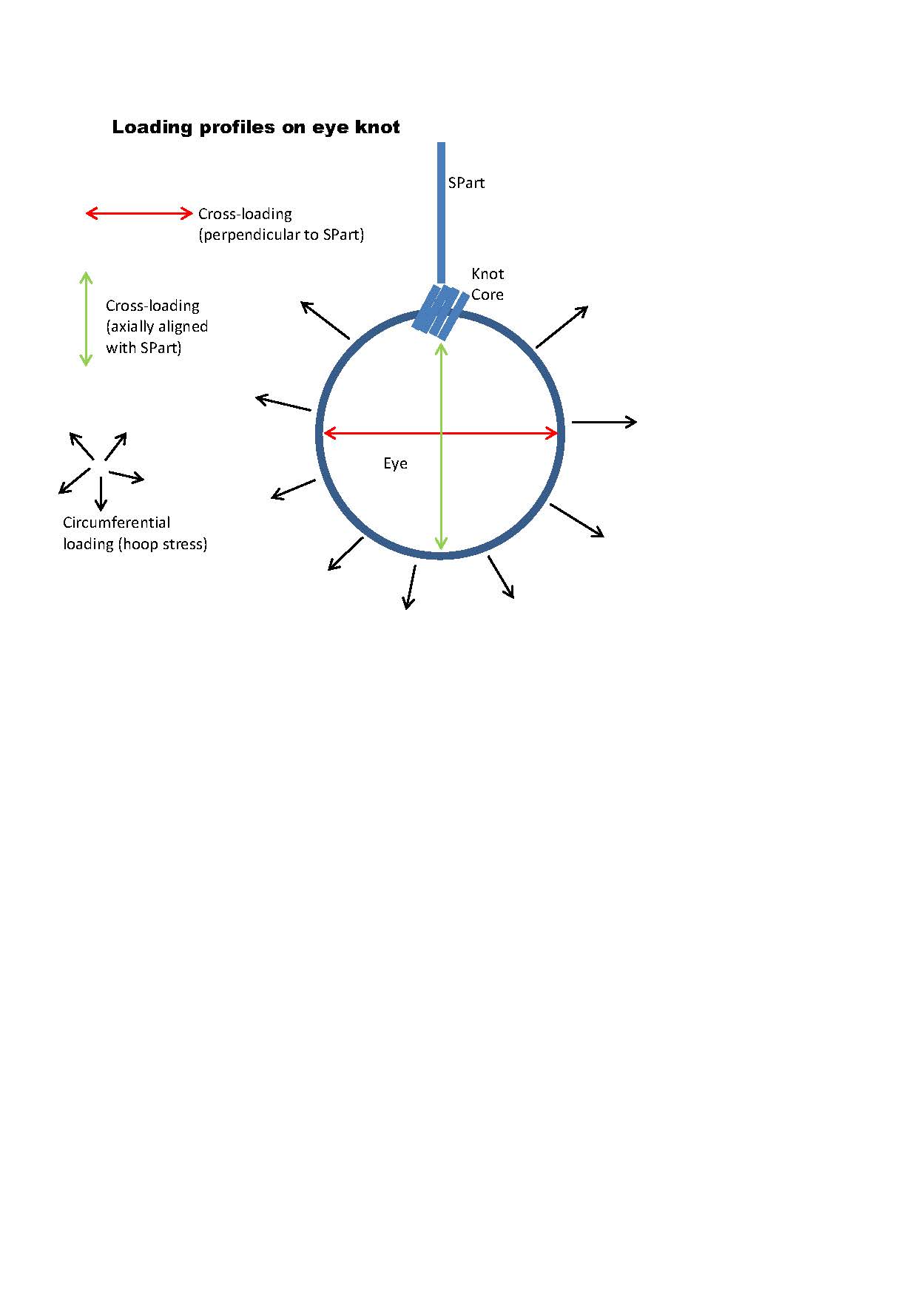
  5. Secure and stable with a solid ring loading profile.

                                                                                [u]Disadvantages[/u] 
    

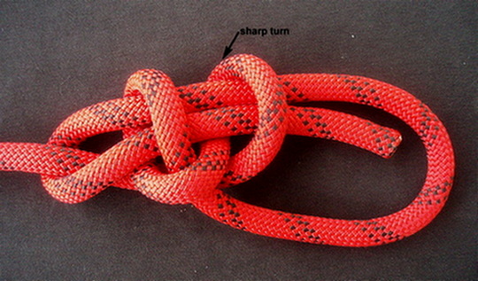
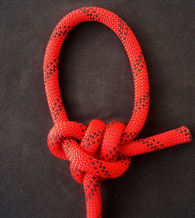
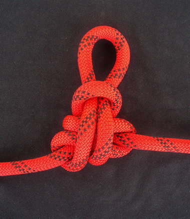
There is a sharp turn, shown in first image, as a continuation of the collar that clamps both bight structure legs, at the second stage of the nipping. This type of reverse clove configuration will tighten the nub quite enough at high loading zones, making the knot more challenging to untie, but eventually, i believe that the pressure will be relieved by pressing the other two collars!

There are also a few ways to avoid the consequences of the sharp turn. To be continued…


It is a very interesting, and beautiful conception.
Until proven feeble, I don?t see this sharp turn as a turn-off.
I noticed that this loop is wonderfully balanced. Both legs when extended fall equidistant to the core and the standing end.
I had no trouble to untie it.
I can wait to see your next improvements.
Great photos by the way.

jr.

Thank you Enhaut, my poor tests show that this sharp turn, is the nub segment, which accumulates more tension, being the most difficult part to loosen, but in the end, i think it is saved by the other two collars of the knot.

I guess, the design goal was to devise a structure that is easier to untie than a double bowline, and if that stands at extreme loadings, when rupture occurs, i think one might accept the extra complexity (if there is any).

However, the first solution in smoothing out this sharpness, is to just tie the Eskimo/anti-bowline.

  1. Doing so, the sharp turn is now bearing 50% of the load, as a continuation of the on going eye leg segment.

2.The SP, is being encircled by the other collar, rendering this configuration less prone to jamming.

Actually, this is the first case i encounter, where the corresponding Eskimo/anti-bowline, appears to function properly, just as the normal one, or even better. :o


The second solution in smoothing out first instance’s sharpness, is to tie the structure shown in the following images.

A long/smoother turn, is now taking the place of the sharp turn, by reshaping the nipping structure with a different internal crossing knot chirality.

Almost the same properties with the original structure, but easier to untie, with a less compact form in terms of aesthetics.

Hello tsik_lestat,

Interesting creation - and your use of the term Virtual Bowline is appropriate (obviously it isn’t a ‘Bowline’ - by a stricter definition).

With regard to your first presentation, I dont see the alleged “sharp turn” as being an issue.
It is an interesting creation - and I presume it is original?

Some points:

  1. I see this as having 1 collar (not 3) - although you could make a strong argument for 2 collars.
  2. In my view, the notional concept of “ring loading” is nebulous.

When a person uses the term “ring loading” - what do they mean exactly?
In most instances, the term is being loosely exchanged with cross-loading an eye.
But, “cross-loading” of a fixed eye can be done in several different directions/orientations.
And there is also circumferential loading (ie hoop stress) - which again could be confused with ring loading.
In your first presentation, I think you might be suggesting it is resistant to cross-loading the eye, to transform the outgoing eye leg and returning eye legs into SParts. In this loading profile, the transformed SParts actually only induce 50% load. To achieve full 100% loading, you would have to cut the eye.

For me, ‘ring loading’ is too nebulous and doesn’t explicitly define the direction/orientation of loading on the fixed eye.

Greetings agent_smith

It is an interesting creation - and I presume it is original?

Thanks, since no one has raised flag so far, the chances of originality are growing, until proven otherwise.

1. I see this as having 1 collar (not 3) - although you could make a strong argument for 2 collars.

You might also consider the nipping structure as a crossing knot + nipping turn, but besides the conventional bowline collar, i think you can’t ignore the internal crossing knot collar component.

In your first presentation, I think you might be suggesting it is resistant to cross-loading the eye, to transform the outgoing eye leg and returning eye legs into SParts.

I had the impression that i was straining the eye against opposite directions in order to observe nub deforming issues. I assume that using your bare hands to apply circumferential loading, might not be the proper way, but the cross loading term, sounds more eligible. Nonetheless, whatever cross-loading orientation is performed to the fixed eye, does not induce observable deformation (even the eskimo ring loading resistance is approached).

Speaking of ring loading resistance, here is the corresponding anti-bowline of the previous knot, which combines the two aforementioned solutions.


tski_lestat:

The term ring loading is nebulous.
Refer attached image.
Cross-loading is more appropriate - but even this must be assigned a direction (it is not directionless).
Circumferential loading means an expansive force acting in all directions on the eye simultaneously (like a balloon being inflated).

Your notional concept of what a ‘collar’ is needs to be properly defined.
By one definition, a ‘collar’ is a component that forms a U-turn around an SPart - and it is braced upon the SPart - which also contributes to stabilizing the nipping loop (or nipping component).

You may wish to define the term ‘collar’ in an entirely different way - and you are perfectly entitled to do so.
It is open to debate - as nobody has attempted to provide a precise definition that is universally agreed upon.
One could go further - and state that there is no universal agreement on any segments or components of knot.
For example, there is no engineering degree from a university where knot terminology is taught and assessed as a unit of that degree.


Loading profiles on eye knot.jpg

Well it shouldn’t be; “ring-loading” should be understood
to mean the loading of an eye as though it were a “ring”,
a closed loop of material,
putting the knot then as an end-2-end joint (with possible
practical situations seeing loading of the eye’s SPart along
with that on the eye qua ring).
And angle is irrelevant, only putting the knot at some
different part of the ring, still in e2e state.

–dl*

Dan, to avoid drifting too far off-topic, I have started a new thread about ‘ring’ loading.

The fourth solution in smoothing out the alleged sharpness, is to tie the reverse, crossing knot based, TIB profiles of both previous TIB bowlines respectively.

  1. Doing so, the sharp turn (first image), is now a direct continuation of the WE, also part of the rope segment that is physical continuation of the returning eye leg structure, thus bearing 50% of the load.

  2. We are actually prooving the EEL ability/property, by visualizing/analyzing their corresponding functional profiles.

  3. A structural resemblance, with the second image knot, shown at first link by Alan Lee, is noticeable, if the WE is pushed out of its collar. It’s like tracking down the Tibness, by capturing the on-going eye leg and then re-threading through the collar.

  4. The second link, points to another relevant knot, with a girth hitch collar, by re-threading through the crossing knot of the collar structure this time.

Link 1 : https://igkt.net/sm/index.php?topic=6832.msg45017#msg45017

Link 2 : https://igkt.net/sm/index.php?topic=6346.msg42633#msg42633

Transposing, the two nipping elements of the first bowline knot, one other virtual structure is being developed, for which i wasn’t able to locate any traces to various knotting sources.

The crossing knot component, is now a physical direct SP continuation, at the second nipping stage, while the nipping turn component, is a direct continuation of the on-going eye leg at the first nipping stage.

Re threading the tug end down through the collar, feeds the virtual bowline world with another TIB instance.

The jamming profile remains stable and unbiased by this nipping structure alternation, however, i wasn’t able to stabilize an Eskimo, out of this bowlinesque configuration :o ???.

Edit note: The nipping scheme, crossing knot + nipping turn, is also known as munter hitch, therefore, a follow up title has been added.


This is an inline presentation of the TIB bowline knot described at the opening post (image 4), but in a configuration of side by side eye legs (or two ends, not crossed).

All one has to do, is to feed the large loop down through the small one to form the knot.(first image)


Excellent post.
We have the “how-to-do” right from the start.
I liked the fact that both working ends bite a 2-rope diameter bight in succession; one over the other.
That TIB nipping configuration is beautiful.
jr.

Thanks Enhaut it looks like we have enough collars to absorb the tension, but i’d prefer the SP, whose continuation encircles the eye legs, would exit the nub in a colinear ongoing orientation with the other SP, but we can’t have it all can we?

Now, how would the knot structure response to a rather strong tensile, through loading force and wether it may accomplish to retain it’s initial shape, i surely can’t predict.

Many thanks for your valuable reexamination.

Nice work tsik_lestat,
Your TIB presentations at reply #11 are opening new lines of thought..very creative!

Some quick observations:

  1. Its TIB - which is nice (Xarax would be impressed too)
  2. It appears to be jam resistant in bi-axial through loading from SPart-to-SPart (it may even be fully jam proof - but this needs to be investigated in a pull it till it yields break test)
  3. In ‘through loading’ - both SParts turn around 2 rope diameters (nice)

In eye loading…
It may be jam resistant (or even jam proof) when eye loaded in both axial directions with respect to either SPart. Testing needs to be carried out to assess this.
Am curious about which eye loading direction may be ‘better’ than the other?
The eye loading direction where a ‘crossing hitch’ links to a ‘crossing hitch’ may be jam proof???

Is there any jam testing that someone can undertake to investigate this TIB mid-line eye knot?
If it ends up being jam proof in any loading profile, it will be of great interest - although a simple tying method must be established - to rival the simplicity of #1053 Butterfly.
The Butterfly is also a superb TIB mid-line eye knot BUT, it jams when heavily eye loaded.

Note: I’ve thrown terms around like ‘jam resistant’ versus ’ jam proof’ without qualifying them.
Jam resistant means the knot can be loaded up to 50% of its MBS yield and still be untied by hand (without using tools) - beyond that threshold, the knot jams.
Jam proof means the knot can be loaded all the way to its MBS yield point - and is still possible to untie by hand (no tools).

Xarax will criticize me about the role of human hand strength within a definition…declaring that the boundary between ‘tools’ and ‘no tools’ is not a useful metric.

Hello agent_smith

1. Its TIB - which is nice (Xarax would be impressed too)

It is very hard to impress Xarax, he is able to decode a knot structure and analyze its components in just a quick peek. :smiley:

He was already sounding concerns about the asymmetry of the SP continuations all along, in relation to this very knot structure, and he is often proved to be precise at his predictions.

Trully, i have recently been informed by Alan Lee, and i am spreading the word to you and apparently to the rest of the audience that follow this topic, that the knot jammed at around 60 % of MBS, therefore it fails to be characterised as a jam proof midline knot, according to your definitions.

However, i am curious of the jamming threshold, at which jamming was initiated, which profile has been tested (it was rather the inline loaded in some way), and how dit it go up to 50% MBS, in order to define its jam resistance. I understand jamming is not a linear process, thus it might occur to any loading phase!

Having been cautious of the sharp turn, it appears according to Alan Lee, that it was the weak link that triggered jamming, while the crossing knot collar did much better, (it didn’t jam).

Based on that, it also appears that i was right to swap the SPs with the Eskimo variation.

Afterall, it was a good TIB exercise, that gave prominence to the versatility of a TIB knot and its various loading profiles.

Thanks for your feedback, and of course many thanks to Alan Lee for his time and effort.

i have recently been informed by Alan Lee, and i am spreading the word to you and apparently to the rest of the audience that follow this topic, that the knot jammed at around 60 % of MBS, therefore it fails to be characterised as a jam proof midline knot, according to your definitions.
Can you please confirm in which loading profile the knot jammed? (I am unclear - so I am asking for clarification). For example, did it jam when through loaded bi-axially from SPart-to-SPart? Or did it jam in an eye loading profile? If jamming occurred in an eye loading profile - in which direction?

I have the impression that it was the inline profile tested by Alan Lee, but i’m also unclear as to how it was tested, SP to SP, or eye loaded and from which link?

I’m pretty sure Alan will provide a clarification note to enlighten us!

Now, back in the OP, i provide one last midline amendment, by making longer the continuation of the more complex previous munter link, in order to smooth the alleged sharpness, which is likely guilty of causing the jamming problems.

Hopefully it might work, but if not, i’m sure there will be found a way to enmesh crossing knot knotting modules for a fully jam proof, inline knot structure development.

The drill is known. Feed the large bight, down through the small one to form the knot, at first image.


@tsik_lestat,
It was standing part to standing part at 50 % MBS just able to untie, at 6o % jam solid.
with 1/4" soft rope can dress the nob tighter then climbing rope, I think for climbing rope
will have lower number. have a quick test on the munter midline loop and it jam solid
around 38 % MBS. I will gather more rope and test all of them. I am not young anymore
need more time to do the test. I am sure will have few good knots this time.