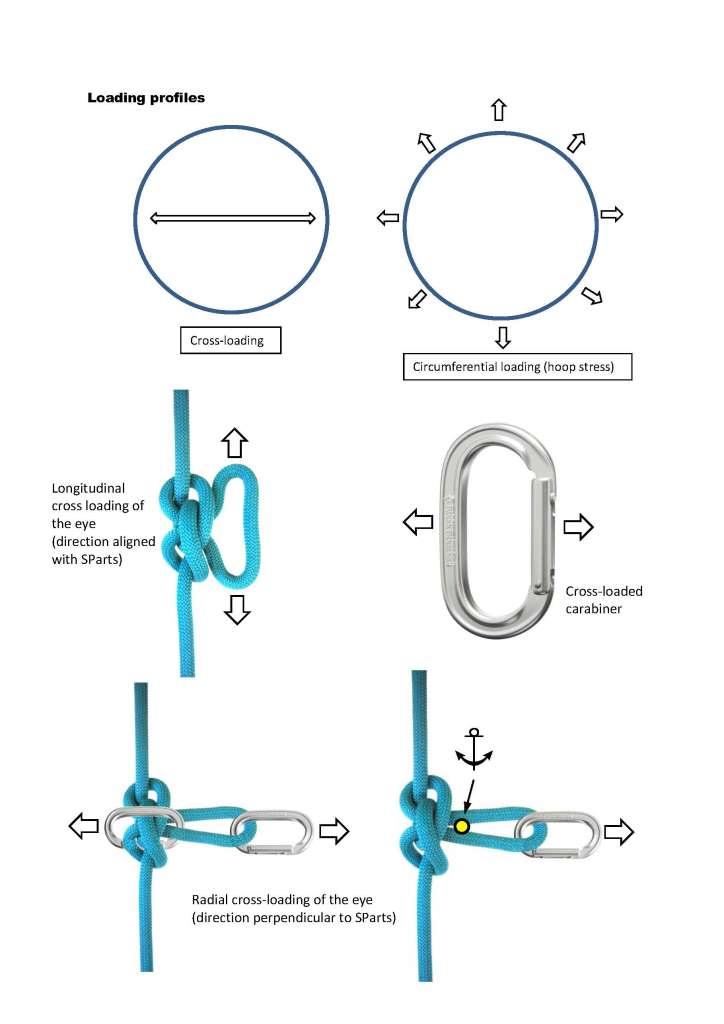
When a person uses the term ‘ring’ loading (on the eye of a knot), what exactly does this mean?
It is likely that when some people say ‘ring loading’ - what they actually intend (ie mean to say) is longitudinal cross-loading.
Perhaps in some instances, they intend circumferential loading (ie hoop stress).
Or perhaps they might intend radial cross-loading?
There is no way to be 100% certain because ‘ring loading’ is ill-defined.
…
Some have (in the past) argued that longitudinal cross-loading of a fixed eye is identical to an ‘offset’ loading profile (a geometry of a ‘bend’ where the core of the joining knot is displaced from the axis of tension) - for example, #1410.
I disagree with this proposition for the following reasons:
A longitudinal cross-loading profile on a fixed eye does not induce a full 100% load on the knot core (load is split 50% across each leg of the eye)
To match the rate and magnitude of loading on the knot core (as a ‘bend’), load would need to be doubled.
I posit that it is not ‘identical’ - rather, it is only an approximation.
I’m a very visual person. I have to draw every written paragraph into a picture to fully internalize what it means. I’m pretty sure my first introduction to the concept of “ring loading” was from your Bowline tome. I thought it was clear to me from you until you’ve made it nebulous right now.
In your tome, you interchangeably used the terms “ring loading” and “circumferential loading.” You wrote, “In fact, it [referring to ABoK 1034 1/2] is resistant to a particular loading profile known as circumferential loading (also known as ring loading).” You even have a picture of “Circumferential (ring) loading” that looks exactly like what you’re now calling “Longitudinal cross loading of the eye.”
I posit that “ring loading” is exactly as you already showed in your tome and what you’re now calling “longitudinal cross loading.” What you called “circumferential” loading in your tome is as you’re now showing (and calling) in your loading profiles sketch. My visual for ring loading is of a free body diagram of a single ring in a chain of rings. Any other loading is perfectly differentiated from ring loading and very clear in your pictorial showing loading profiles.
Only in your mind; others know exactly what is
meant, which you show as “l.cross-loading” --i.e.,
loading the eye qua ring such that the knot is
loaded qua end-2-end joint. That any given
load on this ring will put about half the force
onto the knot in no way distinguishes the loading
from that were the knot directly, unassistedly loaded.
(Btw, how do you explain your “radial cross loading”,
which has the rope in same orientation of “triaxial loading”
except there’s nothing to provide for opposition to the
loaded eye in the former --is the knot to be stoppered
against something ?!
)
Perhaps in some instances, they intend [i]circumferential loading[/i] (ie hoop stress).
Or perhaps they might intend [i]radial cross-loading[/i]?
I surmise that the former almost never occurs,
and the latter I questioned above as to What ...?
But the simple point is : the eye legs are loaded
in opposition to each other (at least in part; whether
there might be also loading of the (proper) end(s)
is possible or not, and might mitigate effects of
the primary loading indicated.
I posit that "ring loading" is exactly as you already *showed* in your tome and what you're now calling "longitudinal cross loading."
The 'tome' which you refer to I presume is my analysis of Bowlines paper?
If yes, it is being updated to include more precise definition of types of eye loading.
Ring loading is too loose / imprecise (in my view).
It takes time and effort to update large and complex papers - but I’m working on it.
My swing away from ‘ring’ loading came about while writing a Knot Bio on the #1053 Butterfly knot.
I realized that it is not precise and can be interpreted in different ways.
All of my papers are subject to update as new ideas evolve (sort of like national ‘standards’ - eg EN892 - which are always subject to review and update).
per Dan Lehman:
Only in your mind; others know exactly what is
meant,
Really!
I didn't know that you are in a position to speak for others?
I'll take that on notice.
That any given
load on this [i][b]ring [/b][/i]will put about half the force
onto the knot
What do you mean by 'ring' exactly.
A ring suggests a circle - ie a geometric shape that is perfectly circular.
Which in turns suggests circumferential loading (ie hoop stress).
I did a bit of research on ring loading and couldn't find any existing science or engineering papers defining it.
However, when I searched for 'load directions' - I got more relevant search results.
This is where I noticed descriptors such as; axial, radial, circumferential, longitudinal...
I surmise that the former almost never occurs,
and the latter I questioned above as to What ...?
All beside the point.
It is possible to place a radial load on a fixed eye.
If using carabiners, one of the carabiners would be positioned directly over the core of the knot.
Whether it "almost never occurs" is irrelevant.
Its simply about describing directions of loading more accurately.
I note that you wrote "almost never occurs" rather than "[i]never [/i]occurs".
This suggests that radial loading profile is still a possibility - however remote.
Dan - at the end of the day, its simply about being more accurate - that is, trying to achieve a higher level of precision.
I think ring loading is ill-defined.
I guess at this juncture, I should challenge you to find exiting engineering literature that defines ring loading? Good luck!
And yes, I will be updating my papers to more accurately define different loading directions.
My upcoming technical paper of #1053 Butterfly will show various loading directions on the fixed eye - and no surprise, I wont be using ring loading
I agree. What you’re now illustrating in your loading profiles are all types of “ring” loading. Calling them out specifically seems appropriate for clarification.
I think you should address this question by Lehman:
The “radial cross loading” sketch is superfluous, in my opinion. In that sketch, you don’t have any loads on the SParts. Can you give an example when that could happen?
I think the “triaxial loading” sketch is sufficient with some modifications. Where Lehman says, “except there’s nothing to provide for opposition to the loaded eye,” I believe he’s referring to the fact that as you depict the loading, that structure is not in equilibrium. Using compass directions to describe the forces, you have a load to the east and two perpendicular forces in the north and south directions. There is no westerly force to resist the force to the east. In actuality, as soon as the easterly force is applied, the forces in the standing parts will be at an angle, that is, one to the northwest and one to the southwest. Those forces will have components in the western direction to resist the easterly force on the eye.
What you're now illustrating in your loading profiles are all types of "ring" loading.
I prefer the following construct:
"I'm illustrating various types of loading profiles on the fixed eye."
I think you should address this question by Lehman:
I did, via this comment:
It is possible to place a radial cross-load on a fixed eye (of a Butterfly).
If using carabiners, one of the carabiners would be positioned directly over the core of the knot.
But, to make it even clearer, refer to attached image.
I’ve shown two different ways a fixed eye (of a Butterfly) could be radially cross-loaded.
However, all of this is missing the underlying point (in my view).
I’m simply trying to be more accurate.
I accept that radial cross-loading of a Butterfly fixed eye is unlikely but, I needed to show radial cross-loading in comparison to longitudinal cross-loading and circumferential loading.
By showcasing all 3, it makes it easier to understand and differentiate between them.
Its also more complete - in that; if you only show one type of loading profile, the picture is incomplete.
By the way, the protrusion caught up in the eye of a Butterfly is not too far fetched.
I recall the ‘ludicrous mode’ testing done by certain individuals hell bent on trying to reveal a vulnerability of Scotts locked Bowline (remember that?).
These people went to great lengths to ‘prove’ that vulnerability (ie by skewing the test to produce the intended result)
Although that type of loading profile is possible (but remote), it does not trigger catastrophic failure of Scotts locked Bowline (I still happily use it on a routine basis).
roo - I was laughing at the time of this alleged test result.
I’m still laughing now…
…
It appears that this thread may now drift off topic and morph into “how to design and carry out an invalid test”?
But - be that as it may now drift:
I’ve never seen a real climber tie-in and lead climb with EN1891 low stretch rope.
I’ve also never seen a competent lead climber tie-in with a loosely dressed knot.
I’ve also never seen how this type of skewed test could occur while rock climbing using Scotts locked Bowline tied with EN892 rope that has been properly dressed and cinched.
Knotting has always had naming problems that has always been ‘cursed’ with/at!
To me, the induced/imposed/initial force(s) are totally contained in the NECESSARY arcs(bind) or not(hitch termination or bend coupling ) in USAGE.
And that force is either focused linear or diffused radial
.
Anything ever stated is from some perspective, even if not formally benchmarked, is a comparison;
to something else, either physical or expectation etc.
Especially as try to ‘grow’ a uniform language across geographies and experiences.
and then too, hopefully matching the world around , that in fact permeates thru the subject in wider perspective.
For knotting, hopefully IGKT is or will be the place looked to for that sorting and defining.
i have problems with some of the names too, yet not the effort.
My first intro to term ‘ring loading’ too was in perspective of the simpler Bowline (in forums) ,
i say ring loading as convention, but to me implies round/radial loading when we oft mean linear lateral (to SPart) loading contained in eye
Such as errantly in standard Bowline or adjusted in anti-Bowline/Alaskan or as i first learned ‘jacked’ (to the side)
so as then model forward from that Bowline lesson as benchmark;
of one ‘axial’ of SPart to opposing end of eye vs. Butter Fly of 3 points of possible pull in normal usages.
.
That is for forces perpendicular, not inline to the ‘proposed’ SPart.
and as we change the direction to ‘opposite geometry’ (not direction) in Bowline, thus need to change flow of the locking mechanism.
By ‘opposite geometry’ i mean from benchmarked location (SPart in this instance) cosine and sine vals swap places.
Of the 0-90degree range median of 45degrees, if we go up/down 15 we have 30 and 60 degrees, equidistant from median.
and the sine of 30 = cosine of 60, and vice versa (median 45 is only point w/o this swap available)
When go up/down 45 from 45 median , we have extremes of 0 and 90, who’s cosine and sine and sine swap, with greatest amplitude possible (Zer0 and Full 100%)
thus ANY time, in linear force, we mechanically go thru that 90 degree change from force input, STOP
and reconsider build, many times to reset to perhaps opposite strategy(like turning lock of Bowline also 90 to match.. ) .
In Bowline, that presents as ‘cross-loading’/ring loading/lateral loading from given perspective of SPart,
pulls the lock of the controlling hitch more open than closed in standard Bowline
thus , then simply change lock direction to capitalize on the new force direction
allowing lock to keep performing as intended
This cross-loading/ring loading across, does contain, w/o SPart it’s own Equal and Opposite pulls
whereby, what once was SPart doesn’t have to be loaded, and in fact if not (while ‘ring’ is)
SPart converts in function to Bitter End (opposite mechanic of sorts)
The re-orientated lock of the hitch, still empowered by pulls in rope, now pulls closed not open
note in normal Bowline pulls, SPart and farthest reach of eye are the E/O paira
Also, in that usage, have external force as a primary, but in ‘ring loading’ primary force is contained, but can be linear or radial input.
.
Bowline , is simpler model of this, as then step up to B’Fly with definitions to test if they persist at this level.
perhaps some points must be re-defined, to then carry back somewhat to Bowline for consistency , before going on past B’Fly.
B’Fly to me is inline/longitudinal is loaded SPart to SPart, then eye can get linear pull parallel to major axis of SParts
or laterally /perpendicular to SPart axial
or unloaded
Loading 1 End as SPart just to eye is quite different, leaving 2nd (formally) SPart, now as a Bitter End.
The ‘Loading Profiles on #1053 Butterfly Knot’ pic of now consistently familiar blue rope (blue fave color, ty):
i think in terms of mostly hitch(termination) and bend(coupling) forms of linear imposed input (SPart)
that is radially controlled, (whereby typical Binding is radial imposed force, radially controlled by contrast)
Thus, where show ‘circumferential’ loading, i would say radial >> but honestly “i” know what you mean/what is in a name?
except, outside of the small pond of knotting, terminology is either focused/linear or diffused/radial loading in physical forces
to invite more serious disciplines, and consistent/comparable verbiage i think we should go w/bigger sea terms
i do think that such loading should be to crossed not parallel leads to eye (as pictured) as most ‘relaxed’ form in B’Fly
as work other pulls on same, would cross if stiffness of rope lent to crossing as more relaxed than parallel
Also to me, a line starts at a point and goes on in linear direction
was actually taught both directions as in keeping w/Ancient Greek terms and writings
but to me, and elsewheres both directions is one loaded axis/axial only
these terms then give differences to line of 1 direction, and axial of competing directions as needed terms.
so sorry, tri-axial to my perspective, is less than accurate, but between us, i now know what you mean.
to me, in this pic, i see both SParts loaded to 1 axis, that eye is pulled laterally across perpendicular to main longitudinal. axis
Eye loading could mean any load pull in eye, vs. not/unloaded as to isolate weak point out of system (not pictured).
tho the same form when tying, completely different mechanical route of force thru to me
i see end to end loading as B’Fly primary construction, eye as lesser if any/ incidental
but in this pic route force from only 1 end thru that locking side to eye
other lock and end to me morphs into Bitter End works, backing up the primary anchored end to eye pulls
Longitudinal /axailly w/SParts is as stated to perspective of ‘SParts’, but NOT the locking mechanism
per locking mechanism of B’Fly, would think this is lateral not longitudinal , but depends on benchmark perspective fair enough.
BUT if ends not loaded, are they SParts?
Same analysis to last pic ‘radial across’ if ends unloaded, are they SParts?
per locking mechanism works, that converts from the end to end single axial to 90 degrees to feed into eye
this is more of a proper, linear pull
and can not visualize usage of pull arrows here, w/o dropping eye thru hole and knot works as shoulders to wide to pass
i hate picking apart every piece so against another fine presentation and effort
but these are my honest gut reactions and reasonings to things i have tried to name w/consistencies to broader perspectives and fields
Also, if loading alone or primarily
NOT a devil’s advocate countering test (that sometimes i do , do; especially internally against own self).
Son w/masters in engineering is not here @4am to ask at this moment, but thru many conversations, starting with questions he carried to instructors in school for me/us etc., i think he would agree with terms as i’ve presented to be consistent with bigger surrounding sea of usages…
Initials in rope, is good and discreet tracer, and also gives tell if blatantly removed, and w/2nd initials not just clip-able from end.
(see missing in last pic of set ‘radial cross’)
i think in terms of mostly hitch(termination) and bend(coupling) forms of linear imposed input (SPart)
I dont think like this at all.
Hitch and bend (end-to-end joining) have different loading and force distribution compared to a fixed eye knot (eg #1047 F8 or #1053 Butterfly, or #1010 Bowline).
Thus, where show 'circumferential' loading, i would say radial
Wrong.
Google 'circumferential loading' (hoop stress).
Eye loading could mean any load pull in eye, vs. not/unloaded as to isolate weak point out of system (not pictured).
? [i]Obviously[/i].
This is what I have been positing.
When discussing load, you need to specify a direction.
Where I indicated simple eye loading, it was to indicate a pull (force) on the eye of #1053 Butterfly - a pulling force will be in a particular direction. In the case of a Butterfly, normally, the force is directed along (in-line with) an SPart (standing part). I think you are misinterpreting simple eye loading of a Butterfly (against one anchored SPart).
i see end to end loading as B'Fly primary construction, eye as lesser if any/ incidental
I disagree.
Rope access operators (refer ISO 22846) [i]routinely [/i]build 'Y hang' twin rope anchor systems that incorporate a #1053 Butterfly - and in these cases, the Butterfly is tri-axially loaded (refer to attached photo). Furthermore, in the outdoor recreation industry, a #1053 Butterfly is often used to create a anchor point on a fixed abseil rope. The eye is than loaded along the direction of the Sparts (one SPart is anchored).
Your imagined through loading of a #1053 Butterfly is simply another example of a loading profile - in this case, the eye is isolated, because load passes through the knot core and there is no net force on the eye legs. A working application of this would be to temporarily isolate a damaged section of a rope.
Longitudinal /axailly w/SParts is as stated to perspective of 'SParts', but NOT the locking mechanism per locking mechanism of B'Fly, [b]would think this is lateral not longitudinal[/b] , but depends on benchmark perspective fair enough.
Longitudinal cross-loading is the correct descriptor.
This is a situation when the eye of a Butterfly is cross-loaded - and the cross-loading is aligned with the SParts.
The reference frame is aligned in the linear direction of the rope length - and each (non eye) rope segment exiting from knot core is an SPart (the legs of the 'eye' are not the SParts).
The terms; radial, longitudinal, and circumferential all align with engineering concepts that explain forces acting on a pipe or cylinder.
These terms seem to fit reasonably well with loading on a fixed eye knot.
What I mean is hitches and bends serve linear force into knot control thru SPart in USAGE
then converts to radial arc from linear in knot to control loadings.
Round Binding usage to me is radial induced loading to radial control by contrast.
all internal no external SPart force input in USAGE.
.
Sorry i base terms on support builds, not pipeline terms
and when use electrical terms of force flow, just to model, not literal
i do see a Y as tri-axial , but not what was shown in orig. pic. with SParts as 1 axis and eye pull perpendicular as 2nd.
Guess I should have said that nicer and politely, sorry.
What I mean is hitches and bends serve linear force into knot control thru SPart in USAGE
then converts to radial arc from linear in knot to control loadings.
Irrelevant.
Read the title of thread.
I stated that ring loading is ill defined.
This is about ring loading a fixed eye of a knot.
Sorry i base terms on support builds, not pipeline terms
?
Its about force and direction of force.
Physics is the underpinning framework.
More brash one-way dictatorship poison into open forum discussion;
that has chased many more than my own back and forth,
away from here over time.
As i’ve watched over the years here sometimes in horror;
constantly ill over the tone and confrontational BS injected.
Always and all ways knowing it shouldn’t have to be like this,
to have to weigh offering insights vs. wading thru all this attitude.
More brash one-way dictatorship poison into open forum discussion
?
What a strange and ill conceived comment.
If the topic is about apples and you steer toward oranges - I am entitled to say it is irrelevant.
You have a habit of straying way off topic.
I’m sorry that you dont like staying on topic.
Always and all ways knowing it shouldn't have to be like this,
to have to weigh offering insights vs. wading thru all this [b]attitude[/b].
?
Another strange comment.
If you wish to discuss hitches and bends - why dont you start a new topic thread and present your ideas there?
From my point of view, it is your attitude that is misplaced.
I'm discussing ring loading - in particular; the various loading profiles on a fixed eye of a knot (eg Butterfly).
Perhaps you should re-read the title of this thread?
I’m sorry that you dont like to discuss this specific concept.
So, back on topic a bit.
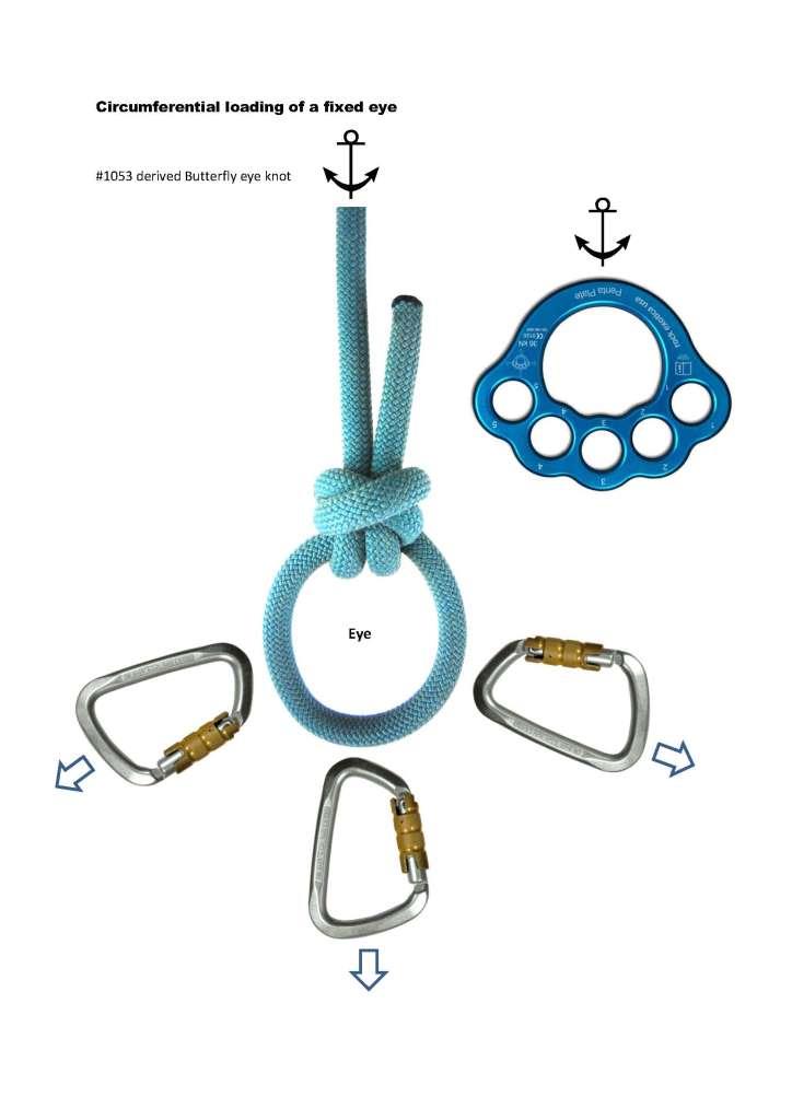
I cannot at this time picture a scenario that uses the circumferential loading profile fully.
Around a pipe? Or something that is expanding?
I cannot at this time picture a scenario that uses the circumferential loading profile fully.
Some vertical rescue teams have used the eye of #1053 Butterfly as an improvised 'rigging plate'.
Some complex 3D rigging scenarios use whats known as a “floating rigging plate”.
A #1053 derived Butterfly (mobius variant) would be suitable for such an application.
Previously, a regular #1053 Butterfly has been employed.
I think the derived Mobius Butterfly would be a better choice for employment as a ‘floating rigging plate’.
Note: I’m using the term ‘Mobius Butterfly’ on account of Xarax stating that IGKT member ‘Mobius’ first presented it.
Anyhow, this would be the closest example of a circumferential loading profile.
And thank you for steering this topic back on course.
My original contention is that the term ‘ring loading’ is not well defined - as it does not specify the direction of force.
It is largely left to the imagination of others to choose a loading direction.
Historically, ‘ring loading’ was likely ‘assumed’ to have been longitudinal cross-loading of a fixed eye. All I am trying to do is define the various directions of loading - so it does not have to be ‘assumed’.
Only in your mind; others know exactly what is
meant,
Really!
I didn't know that you are in a position to speak for others?
I'll take that on notice.
Not speaking FOR them, but WITH/To them,
and understanding them in return. We do not
stumble over "ring-loading" in the least; you,
however, are working overtime to try to do so
--take note of that!
It is possible to place a radial load on a fixed eye.
But the effect upon the [u]knot[/u] is to load it
qua end-2-end joint, which IS the point (of the
definition). We are concerned with the KNOT,
not the eye, per se.
I think ring loading is ill-defined.
I guess at this juncture, I should challenge you to find exiting [i]engineering literature[/i] that defines [i]ring loading[/i]? Good luck!
Why would we be looking there? The term comes not
from the engineering world, but the rockclimbing one;
and we can see there clearly what is meant --meaning
is use.
In this case, you missed your call out of 'bingo'!
I will be updating the alleged 'tome' that [i]keystoner [/i]referred to.
The term 'ring' loading will take more of an anecdotal role - and be replaced with more specific directions of force.
[b]We [/b]do not
stumble over "ring-loading" in the least; you,
however, are working overtime to try to do so
--take note of that!
I see that you are using "we" again.
Sorry Dan, I'll simply ignore your retort of 'take note of that' (there is nothing to take note of).
Not speaking FOR them, but WITH/To them,
and understanding them in return.
You are indeed a spokesperson. Very impressive...
While you are speaking WITH "them" - inform 'them' that agent_smith is simply looking at ways to define the direction of loading on a fixed eye.
[b]We [/b]are concerned with the KNOT,
not the eye,
?
Although 'you' may be referring to 'we' and, you now appear to deflect the discussion to a [i]knot[/i]...
I on the other hand am referring to direction of loading on a [i]fixed eye[/i].
It seems that 'we' are discussing two different topics.
[ ] I made it clear that I am discussing the direction of loading on the [i]fixed eye[/i] of an eye knot
[ ] You (or the 'we') now appear to morph that discussion to a 'knot'?
Why would we be looking there? The term comes not
from the engineering world, but the rockclimbing one;
?
Ring loading (of a fixed eye) does not come from any physics or engineering book because it doesn't exist.
And it doesn't (or rather didn't) come from the rock climbing world either... it came from this forum.
The only reason why a select few rock climbers might use that term (ie ring loading) is because it has filtered down via this forum.
Dan,
Not sure what your ultimate purpose is?
Maybe its as simple as defending your current understanding of ring loading and resisting any notional change of redefining it?
In my mind, ring loading a fixed eye of a knot is not well defined and could be arbitrary.
Assigning a direction to the force makes sense to me…
Since you’re so concerned about clearly defining terms, let me suggest you study the definition of ‘ignore,’ since from my perspective, instead of ignoring Dan’s retort, you did the exact opposite. You felt the need to respond and let the entire forum know. From my perspective you have an insecurity that causes an incessant need to get the last word. See, you’re the common denominator. Every time there is anything contentious in this forum, you’re involved. It’s getting old and boring and makes it no-fun to read threads you participate in.