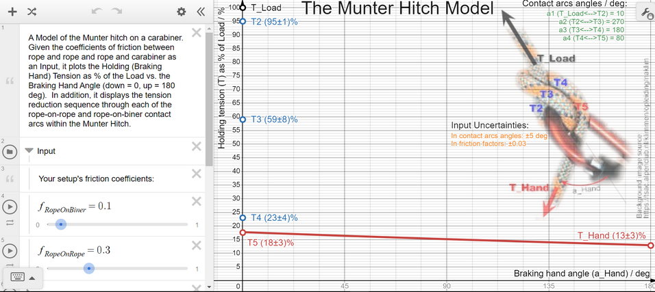
Given the coefficients of friction between rope and rope and rope and carabiner as an Input, it plots the Holding (Braking Hand) Tension as % of the Load vs. the Braking Hand Angle (down = 0, up = 180 deg). In addition, it displays the tension reduction sequence through each of the rope-on-rope and rope-on-biner contact arcs within the Munter Hitch.
Normally, only Input friction parameters need adjusting, but you can adjust any values and equations within the Model at will.
To reset, reload the link above.
Various ‘what-if’ scenarios can be evaluated using the Model, including:
Am I going to be able to hold the load even with the breaking hand angle of 180 degrees or is my rope/biner system too slippery for that?
Is it better to increase rope roughness or the biner roughness to increase the total friction of the Munter and lessen the breaking hand tension?
Does the difference in load reduction by moving the breaking hand all the way up from the down position suffice for the application?
A niche use: if you know f_RopeBiner and have measured F_Hand / F_Load ratio of the Munter, you can estimate the f_RopeRope by adjusting it until the graph matches your measurements (usually at a_Hand = 0 deg). Measuring the f_RopeRope friction coefficient directly prior to using it with the Munter Model is preferable as this reduces the uncertainty of its value https://www.desmos.com/calculator/rqq1zb0e6b
Very excellent thank-you for late Christmas present!
i must still go over many times!
Wonder how much rope stiffness plays per tension as rope lends to or fights against fullest seating frictions
like showing stiffer rope grinding wider to seat more to carabiner host sides less to interior of bight,
rather than grinding of rope against rope where they contact points move more in opposing directions
But wonder about not only if opposing directions at control leg is spread vs. touching/ how much,
but also if control leg is not side by side but crossing over .
.
(s)light tweak and have calcs for Backhand Turn , a more used modular base component of other architectures(faves: Pile, Sailor, Icicle family) or even in reverse in usage to maintain/lock off as in new fave quick re-lease of Tumble.
To this view can show each as input/outputs to same base component machine of same set geometries of these same materials , extruding same usable CoFs and degrees of seating contacts and areas.
Other variables of how linear vs. radial contact profiles of both host and rope still matter.
.
To me 550 paracord is rounder on linear yet flattens when that linearity is deflected to deform to flatter contact profile
but, same ‘sausage’ stuffed denser to 750 pracord maintains it’s roundness
Flattening on arc gives less leverage against rope at the deformity etc. in HH model
but more deforming against SPart in same HH I think
This is easier to see/model in webbing as magnified expression to microcosm of 550
550 brings closer to more organic round ratioing, even to more squared if doubled because flattens only to half as thick as is wide.
not paper thin to 4" wide ratio of most linear/no rounding type aspect
i think each of these things matter, and always watch radial vs. linear at any point in anything.
Just wanted to mention that I added the uncertainty propagation to the Model and added some diagnostic info to the display.
You can estimate now how good your model predictions may be given what you realistically know about the measured, and thus uncertain, inputs (friction factors and contact arcs).
It’s also educating to play with the values of Inputs and their uncertainties and see how much impact would they have on the uncertainty of the results.
For instance, if your measured value of rope-on-carabiner friction factor is some 0.10 +/-0.02 (a typical, optimistic uncertainty - the reality is likely somewhat worse - which means that you believe that your friction factor value is somewhere between 0.08 and 0.12 but you don’t know where) you will likely find that although it affects the uncertainty of the results slightly, it doesn’t really matter that much in interpreting the Model’s results.
Another application of the Model can be on the Backhand hitch which is the same as the Munter with 180deg braking hand. I looked at the data from How to Reduce Jamming - KM146:pp.24-30 and the Model seems to simulate the Backhand hitch fairly well (measuring the rope-on-rope friction coefficient value more directly would probably improve the fit).
p.s. This may be of interest to Derek’s work: In the paper above you can compare the performance of the round turn with the Munter/backhand turn (which more or less differ by the rope-on-rope junction section) to deduct the rope on rope friction coefficient. Done on a napkin, it seems close to 0.15 for my setup back then - surprisingly low to me as it is similar to the rope-on-bollard friction factor - I expected higher - but possible for this setup.