Ampersand TIB bowline

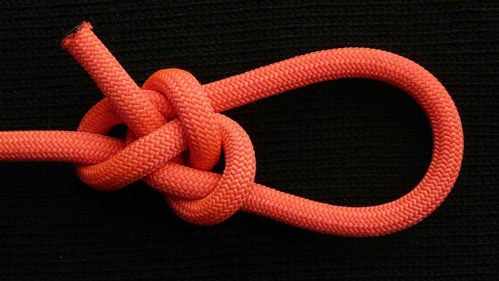
After losing some more time in practicing the usual tit-for-tat among knot tyers, it is about time to proceed, and tie some knots ! :slight_smile:
A bowline-like PET loop is a versatile and a useful knot - so a TIB PET loop, is even more versatile, and at least as useful as a non-TIB one. It would be great if we could discover and tie the same ONE knot ( instead of tying two different knots ) either when we want/need to tie a loop in the end of the rope, or when we want/need to tie a loop in the bight, in the middle of the rope - provided, of course, that we do not jeopardise the qualities required from the different knots we are accustomed to use in each of the two cases.
There are many PET TIB loops we already know, and, as I believe, there are many more that we will discover in the future. The eyeknot presented in this thread was known to me for some time now, but I had not noticed that it was TIB - probably because I was not searching for PET and TIB eyeknots when I had first tied it. You have to be lucky to tie a new knot, but “Chance favors the prepared mind”, and, at that time, it seems that my mind was not prepared yet for this… :slight_smile:
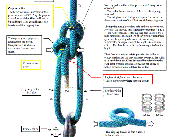
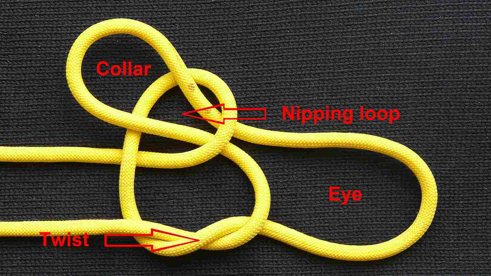
It is a very simple two-collar secure bowline, but it is somehow tricky, because the Tail End is not going through the nipping loop, as it happens in most similar eyeknots - and that is what could had been, I think, the main reason it has not been tied already - iff it has not been tied already, of course.
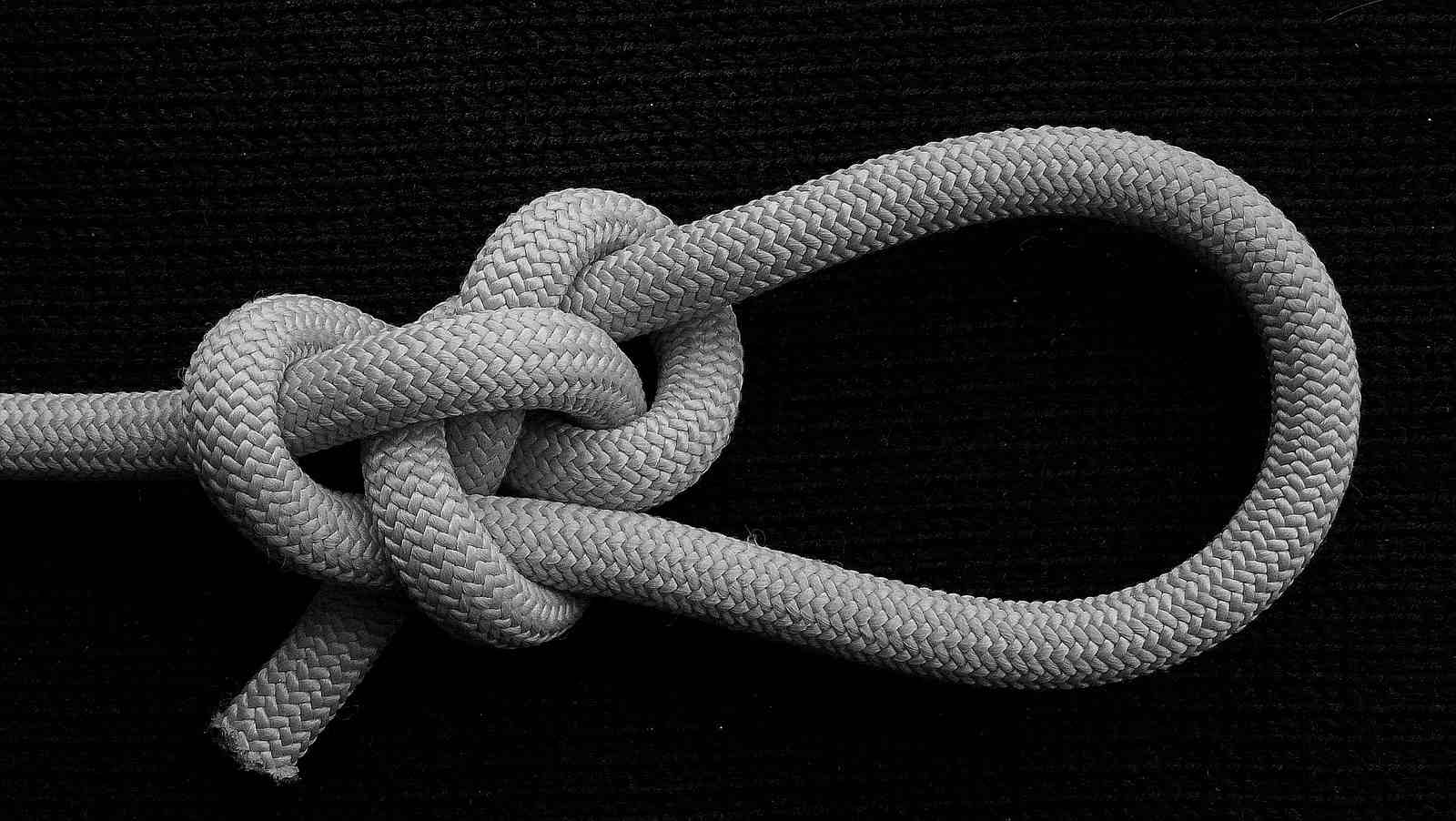
At the present, it is my favourite mistress / loop :slight_smile: - and I say mistress, because I think of the loops as having a female gender… Perhaps this is due to the two adjacent o s in the word “loop” :slight_smile: - or to the fact that, in my native tongue { in which I translate, using the Google translator, as it was kindly suggested to me by roo, everything is said against me in this Forum, in order to become able to understand it :slight_smile: }, the ancient and modern Greek word for “loop” is “θηλεια” [/i]( pronounced : thileia ), which is etymologically directly related to the word “θηλυκο” ( pronounced ; thiliko ), meaning “female”. Now, why on earth somebody would had ever thought to relate the “loop” to the “female”, is something I leave to the imagination of the reader.

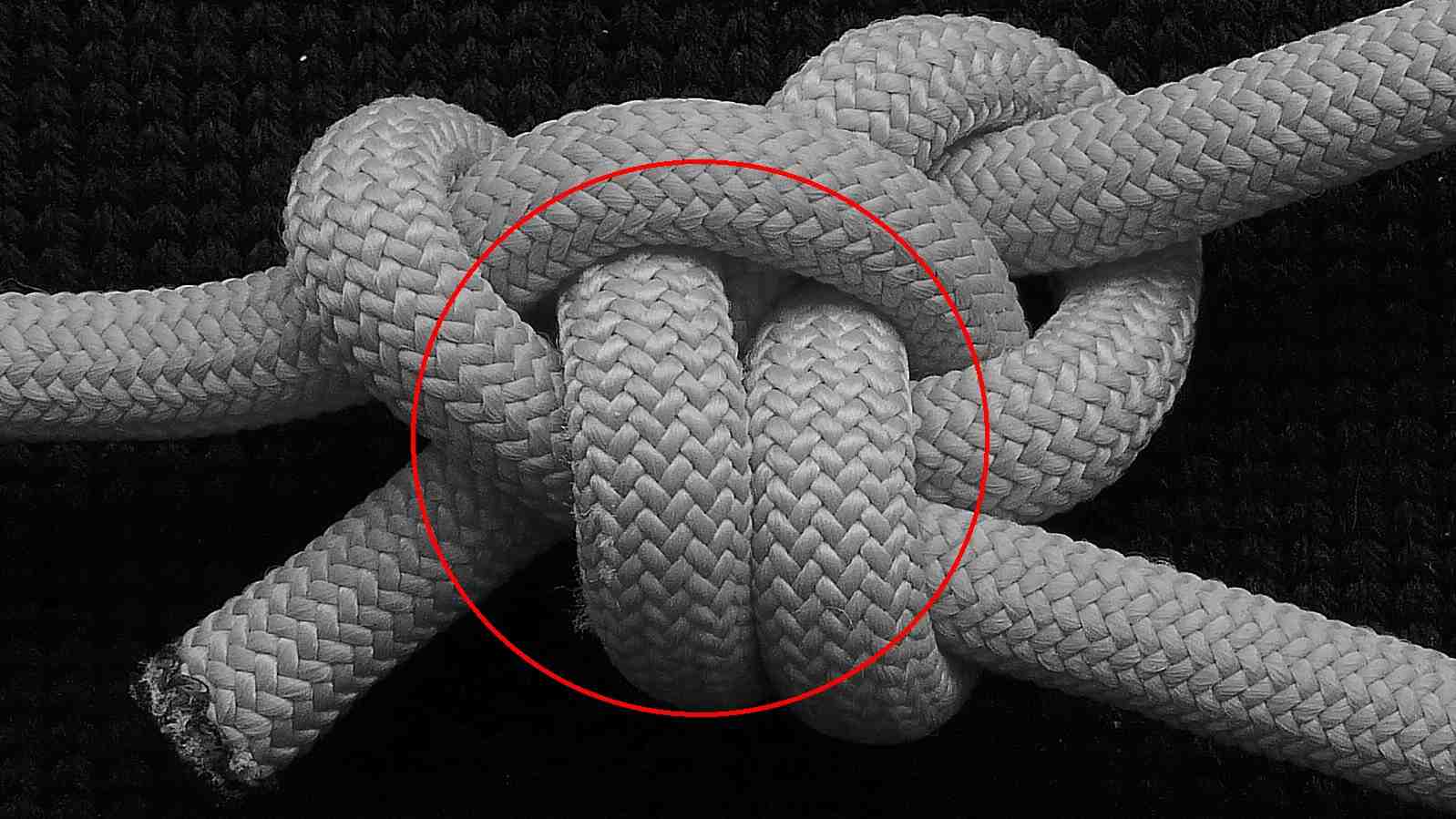
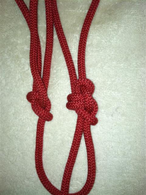
P.S. Perhaps in order to rime with the two o s, or in order to be stronger, the same loop can be tied with two nipping loops ( = a double nipping loop ). I had decided to present only the single-nipping-loop version in this post, so the reader would not be confused with the more complex image of a double Ampersand loop( two collars + two nipping loops). Also, as we have not yet tested the theory, that a double nipping loop is really stronger than a single one ( based upon the idea that, in such a double nipping loop, the distribution of the tensile forces coming from the Standing End, which is loaded with 100% of the load, would be spread more evenly along the rope and inside the knot s nub ), I believe we have to be cautious in suggesting such double nipping loop bowlines. Having said that, I would like to mention that, in the double Ampersand loop, the Standing part is following a very gentle curved path before it winds up and forms the two nipping loops, and that may also be beneficial to the strength of the loop.


Ampersand TIB bowline ( front view ).JPG

Ampersand TIB bowline ( front view ) (B&W).JPG

Ampersand TIB bowline ( rear view ) (B&W).JPG

See the attached pictures of the Double Ampersand bowline, where this “very gentle curved path” is clearly shown.


Double Ampersand bowline (2).JPG

Double Ampersand bowline (2)(detail).jpg

I believe this variation to be a secure addition to the bowline family.

That said, I don’t believe that a strength increase is what necessarily follows. The dual coil nipping area may give a cushioning effect, but that will allow more frictive crushing to occur.
And it doesn’t actually change the contested area of failure’s angle.

Consider the offering of Mark Gomer’s “Analysis” I have attached.

Also, tie a #1010 standard bowline and this or a “water bowline” and compare the two at this place indicated by the red arrow in the attachment while pulling them very taught. The interference angle is the same, to my eyes.

I would like to see how this would perform in the “magic rope” :slight_smile: due to its perceived security increase.

SS


mgba (Small).gif

What this gentle curve is supposed to do, is to reduce the amount of load which is directly applied on the one end of the nipping coils s “first curve” before the tensile forces reach it. That is, to insert an intermediate additional, new curve, in between the Standing end and the nipping coil : in short, to make the previous sharp “first” curve, second ! :). Even if this added gentle curve is very wide, it may work as a cushion, which will absorb a part, however small, of the total amount of the tensile forces running through the line, and will distribute it on its adjacent / surrounding segments.
Am I sure that this will happen ? That this gentle curve will not be straightened up, during heavy loading ? That, even if it will remains curved, it will not be rotated, as a whole, as a solid arc, and just deliver to its second, lower end exactly the same amount of load which is inserted into it at the first, upper end ? Nooope ! :slight_smile: Although a knot seems such a simple thing ( knots were invented tenths of thousands of years before the wheel…), as a mechanism, it is very complex - we do not even know the exact form of the path of the rope in a compact overhand knot !
The fact that the rope will probably break or melt at another point, and not at a point along this wide intermediate curve or the sharp “first” curve at the area of the nipping coil, does not mean much, IMHO. I believe that the ropes do not break at the area of maximum loading - but also that it is this area of maximum loading which triggers and propagates the breakage.
It may be proved that all this will be proven to be nothing but hand-weaving arguments, OR that it is a sound theory, indeed - all that is required, is a series of careful , unbiased, repeatable tests ! :slight_smile: We have the knots, we have the knot tyers, but we do not have the knot tests, so we our basis where we think we stand is not so stable, I am afraid !

What this gentle curve is supposed to do, is to reduce the amount of load which is directly applied on the one end of the nipping coils s "first curve" before the tensile forces reach it. That is, to insert an intermediate additional, new curve, in between the Standing end and the nipping coil : in short, to make the previous sharp "first" curve, second ! :).

Putting this conjecture to a simple hand strength test, comparing this latest offering and the standard bowline, I don’t see any meaningful difference in the approach angle leading to the hard nip first curve. In fact depending on how hard one dresses this knot, the angle just after the standing part enters the collar is more severe. See photo attached.

I believe that the ropes do not break at the area of maximum loading - but also that it is this area of maximum loading which triggers and propagates the breakage.

Care to elaborate on the quote?
I don’t believe that we can eliminate the starting or ending point of a rope breaking. It is at that maximum load (at a specific time that may not even be the equal of the rope’s stated or unknotted test breaking point) that the chain of failure events lead to rope degradation.

Imo, for synthetic cordage, it is a melting of a few fibers that pass their heat to the neighboring fibers and so on…
In natural type fibers, the load released of one is then passed to the next and so on…
For slippery HMPE the straight line molecular bonds, which are so darn strong, do not like curves and so give them up in severe turns. Add poor heat resistance to this and we can see the need for the slippery coatings. http://en.wikipedia.org/wiki/Ultra_high_molecular_weight_polyethylene

If there were enough tests done (whenever they are), I believe that the greater portion of the failed bowline style loop knots will have broken in this load nexus area.

SS


firstcurvecomparison.JPG

THAT was the subject of my previous post ! :slight_smile: I did not say anything, anywhere in the previous post about " the angle of approach " ! ( If there was something before the first curve, to make it wider, I would had characterized it as a “deflexion” ). I said something about an intermediate curve, which is NOT supposed to make this angle wider, but …( Here, you are referred to the previous post ! :))

Also, my comparison, right from my first post, was between the single ( = one nipping loop ) and the double ( = two nipping loops ) Ampersand bowline. The second coil ( of the double Ampersand bowline ), makes the inserted intermediate curve longer, so wider ( than the corresponding curve of the single Ampersand bowline ). ( Read the P.S. of the first post )

The point of the line where the rope breaks is not at the location of the maximum tension - so those two events do not coincide spatially ( or, for that matter, they do not coincide temporally, too, because there may be an hysteresis between the moment the maximum loading is applied, and the moment the rope breaks ). HOWEVER, it is the later which is the cause of the former - but in a strange way we do not know, what happens in the point of maximum tension/elognation triggers the initiation and development of the many complex phenomena that lead to the fracture of the material = the rupture of the line, far away from the source of the whole event. About this issue, I know as much as everybody - that is, next to nothing ! In engineering, when we have such complex catastrophic events, far away from the region of the elastic deformation of the material, the only thing we can do is to raise the margin of security…That is how the “working load” has been lowered to even the 1 /15 of the MBS ! :slight_smile:

So, let us insert some oil in between the fibers, to cool, locally, the heated area, by dissipating the heat generated there within a greater volume ! Try it, using a humble syringe ! :slight_smile: (1)

  1. http://igkt.net/sm/index.php?topic=4246

    P.S. The single nipping loop of the common bowline is more free to twist around itself, and so it can be oriented and settle in a position where the deflexion before the first curve is substantial, indeed. The double nipping loop bowlines * the “nipping tube” ) is more rigid regarding this, so both coils are forced to remain at right angle with the Standing Part, and this may lead to a smaller deflexion, and a sharper first curve. You win something, you lose something - the question is, do we really win anything at all, by this duplication of the nipping loop ?


Stress_Strain_Ductile_Material.png

Colombus syringe.jpg

THAT was the subject of my previous post ! :) I did not say [i]anything[/i], anywhere in the previous post about [i]" the angle of approach "[/i] ! ( If there was something before the first curve, to make it wider, I would had characterized it as a "[i]deflexion[/i]" ). I said something about an intermediate curve, which is NOT supposed to make this angle wider, but ...( Here, you are referred to the previous post ! :))

Approach angle was my term, yes. And I was talking about the double loop version.

Also, my comparison, right from my first post, was between the [i]single [/i]( = one nipping loop ) and the [i]double[/i] ( = two nipping loops ) Ampersand bowline. The second coil ( of the [i]double Ampersand bowline[/i] ), makes the inserted intermediate curve longer, so wider ( than the corresponding curve of the [i]single Ampersand bowline[/i] ). ( Read the P.S. of the first post )

I did read the entire writing, including the P.S., I just went on from a further point in the discourse. The angle where I see the challenge is not between the collar and the nipping loop, it is at the nipping loop where the standing part and working part contact.

Your quote, not mine

The point of the line where the rope breaks is not at the location of the maximum tension - so those two events do not coincide spatially ( or, for that matter, they do not coincide temporally, too, because there may be an hysteresis between the moment the maximum loading is applied, and the moment the rope breaks ). HOWEVER, it is the later which is the cause of the former - but in a strange way we do not know, what happens in the point of maximum tension/elognation triggers the initiation and development of the many complex phenomena that lead to the fracture of the material = the rupture of the line, [i]far away[/i] from the source of the whole event. About this issue, I know as much as everybody - that is, next to nothing ! In engineering, when we have such complex catastrophic events, far away from the region of the elastic deformation of the material, the only thing we can do is to raise the margin of security...That is how the "working load" has been lowered to even the 1 /15 of the MBS ! :)

And why wouldn’t the point where the rope breaks not be the maximum tension achieved at that moment? It makes sense that the load would be relatively equal up to that position, in these knots, on their standing parts. Then the knot performs a drastic change in load dynamics.

In this link http://iopscience.iop.org/1367-2630/9/3/065/fulltext/ it shows what is happening to a monofiliment, which is what a rope is made of (many of them bundled), so extrapolating out from the single filament that breaks, the next and next do so as the load is transferred to them.

My thought is that the inner section of synthetic rope is crushed to a point of high enough temperature to melt, allowing the molecular bonds to release, then the subsequent tensile parts tear.
With natural fibers, it will be the fibers with the greatest tensile strain, the outer ones.

[quote="SS369 post:5, topic:5224"] Imo, for synthetic cordage, it is a melting of a few fibers that pass their heat to the neighboring fibers and so on... [/quote] So, let us insert some [i]oil[/i] in between the fibers, to cool, locally, the heated area, by dissipating the heat generated there within a greater volume ! Try it, using a humble syringe ! :) (1)
  1. http://igkt.net/sm/index.php?topic=4246

There are thermal images that show this heat http://www.youtube.com/watch?v=s3fHYGY3YTo and I don’t know that adding a contaminate is useful at this stage of non-testing. :wink:

P.S. The single nipping loop of the common bowline is more free to twist around itself, and so it can be oriented and settle in a position where the deflexion before the first curve is substantial, indeed. The double nipping loop bowlines * the "nipping tube" ) is more rigid regarding this, so both coils are forced to remain at right angle with the Standing Part, and this may lead to a smaller deflexion, and a sharper first curve. You win something, you lose something - the question is, do we really win anything at all, by this duplication of the nipping loop ?

I still believe that both loop knots are going to try and straighten this curve at the nipping area.
In fact if you look at the single nip vs. the double, the standing part has a lower angle. The single approx. 45 degrees and the double near 90. Perhaps that is a contributor to the latter’s security, but not necessarily breakage inhibition. Unless the doubled material does indeed provide a non-detrimental cushioning effect. (?) Although it changes the angle at just inside the collar. (Which could then be the point of break.)

SS

You mean, “where the continuation of the Standing end, and the continuation of the returning eye leg” contact. Yes, this is right on, or very close to, the area of maximum curvature. It is good to try to make this angle wider, but, as I said, when you have a semi-rigid nipping “tube”, which is forced to be aligned / remain parallel to the Standing End, you have to make a 90 degrees turn, so you can not do much. The humble common bowline, with its ability to twist the plane of its single nipping loop, can adjust itself better, as you had noticed. As I tried to explain in my previous post, the wider angle of the single vs. double bowlines, in general, should be expected. As you say :

However, I repeat that my point was about the intermediate arc, the added longer and wider curved segment, not about the angle of the first curve.

( Also, I had not said anything about the angle “between the collar and the nipping loop” ! I can not even imagine if this angle ( meaning, the angle of the two corresponding planes ) has anything to do with anything ! :slight_smile: )

I know ! :slight_smile: I tried to elaborate a little about this quote, as you had asked me to do.

Good question - if this question is not a rhetoric one. I do not know, and I have not found anybody who knows much more ! :slight_smile: However, this is what is happening, indeed :

http://iopscience.iop.org/1367-2630/3/1/310/fulltext/

P.S. Thanks for the link. Very interesting ! I should had known this - and perhaps I had, indeed, in the past, but I have forgotten it… This is how one can SEE inside the rope - which is something it would be great if we could apply in the many superficially “similar”, yet altogether different knots we have.

I had read this article in the past, but I have not found it very useful - so it was expected that I will forget it soon ! :slight_smile: It is about a correlation between the crossing number of stoppers and the point where they break - something that it is interesting, but can not be generalized in the case of a bend or a loop knot, for example ( where we have more than one loaded strings, entangled to each other, some of them been loaded by the one side only, etc. ). I re-post its conclusions here, for an easily accessible summary.

Effects of knot characteristics on tensile breaking of a polymeric monofilament
Hiroki Uehara1, Hiroyuki Kimura, Asami Aoyama, Takeshi Yamanobe and Tadashi Komoto
Department of Chemistry, Gunma University, Kiryu, Gunma 376-8515, Japan

Conclusions

When the torus series of knots were made in a PVDF monofilament, the tensile strength gradually decreased with increasing crossing number. The two reasons for this phenomenon were squeezing and rotation of the filament. At lower crossing numbers, the knot was significantly squeezed due to the lower rotation of the filament. Therefore, breaking occurred at the shoulder position within the knot, where the highest bending was obtained. When the crossing number was increased, the enhanced filament rotation induced torsion within the knot, resulting in breaking at one of the entrances of the knot before squeezing into the entire knot. These effects of filament squeezing and rotation led to a breaking-position shift from inside to outside the knot with increasing crossing number. These results suggest that both squeezing and rotation, which are characteristic for a given knot, dominate the breaking position of the knotted strands.

New Journal of Physics 9 (2007) 65 (http://www.njp.org/)

Good question - if this question is not a rhetoric one.
Not a bit. Even if the break is minutely away from the initiation point, that point is still part of it. So, that has to be the maximum load attained, regardless of the rope's breaking strength.

You’re welcome, for the link. It is interesting and I believe I’ve shared it before elsewhere. Memory is a fleeting thing, I know. :wink:
The thermography with the Fig 8 testing video is eye opening too.

However, I repeat that my point was about the intermediate arc, the added longer and wider curved segment, not about the angle of the first curve.

I’m unsure what you mean in the above, apparently.
The longer curved segment I see in the knot is between the collar and the nipping area, ultimately straightens out under higher loads or closer to straight in the double nipping “tube” variation, whereas the single nip allows even a straighter standing part respectively.
Perhaps it does shed some minute amount of force into the nub body. (?) Infrared imaging might just show this.
Maybe there is a smart phone app for this. lol

SS

I think this quoted conclusion helps to sell a braid more than a knot or why a splice is so strong.

But, the following quote is very informative. "Up to now in our considerations we neglected the effect of friction on knot breakage. Tightening of real knots is opposed by increasing friction between segments that are pressed together. At some point this friction can be so strong that the string entering a knot will rather break than move further. Therefore real knots may never reach the maximally tight form which could be obtained with ideal frictionless tubes. Studies of the friction in knotted ropes [12] demonstrated that friction is greatly enhanced in the contact regions with high curvature. Therefore when the contribution of friction is not negligible the regions with high curvature at the entrance to the knot will effectively block further tightening of the knot. The level of possible tightening of real knots depends on factors such as the coefficient of inter-segmental friction and the strength of the material from which the knot is made. We decided to follow changes in the curvature of knots during their simulated tightening, although in our simulations friction was not present. Figure 7 shows sequential maps of curvature of a simulated overhand knot during its tightening and the simulated trajectories of overhand knots corresponding to the first and last curvature profiles obtained during progressive tightening. It is visible that both shapes can be considered as very tight and are practically indistinguishable upon visual inspection, however there are differences in the position of the regions with highest curvature (see the colour coding). In a slightly loosened knot the highest curvature is localized shortly after the entrance to the knot and its position corresponds to the experimentally observed breaking points in knotted spaghetti (see figures 5 and 6). In the maximally tight state (that may be only accessible to very slippery materials such as fishing lines) the region of highest curvature is localized deeper in the knot. "

SS

I do not see how the first sentence implies the second ! There is a point A, where there is a maximum tension. OK. There is a point B, where the rope starts to break. OK. Why should those two points have to be the same ? If there is flow of temperature involved, vibrations and minute shock waves, propagation of microscopic cracks, etc, there will be a lot of other factors that can separate those two points, causally, spatially and temporally.
I believe that the situation is far too complex to be analysed in separate, partial images, which can then be brought together and paint a coherent larger one. In general, I do not trust the approximations one is forced to accept in his effort to explain the phenomena in such critical situations, because one can not predict how a minute, apparently insignificant side effect can nevertheless trigger a whole cascade of significant ones, and lead to a catastrophic failure. To the degree I can follow the “reasoning” of such analyses, there is too much of hand-weaving arguments and over-simplifications… At the end of the day, nobody has ever predicted where exactly a tensioned overhand knot will break, for KnotGod s sake !

First : HOW MUCH will it be able to straighten out ? It is not alone in empty space, there are other loaded segments near by, forcing it to bent, and remain curved.
Second : Even if, at the end, it will be straightened, would nt it be the case that, in the mean time, during that straightening ( which will not happen instantaneously, of course…), the friction between it and the adjacent segments would have already absorbed a portion, however small, of the impact of the loading force ? Imagine the possibility of an elongated knot, where we can have many such arcs formed in the direct continuation of the Standing End, the one after the other. The whole knot will be able to function like a spring absorber, because the force that will be required to straighten out them will be subtracted from the force that will be able to reach the sharp curve after them - which now we can not even call “first” curve !

In short, one thing is to try to make the angle between the straight continuation of the Standing End and the start of the nipping “tube” as wide as possible. A second thing is to try to make the nipping coils themselves as wide as possible, so the “first curve” will be less sharp. A third thing is to insert some “deflexion” in the recipe, so the continuation of the Standing End is not parallel to the axis of loading, when it reaches the “nipping tube”, which is aligned to it, more or less. And a FOURTH thing is to insert an intermediate, however small, wide curve in between the straight Standing End and the “first curve”, which can work in tandem with the later, and absorb some tension before it reaches the more critical points.
As you might remember (1), I had even tried to make the continuation of the Standing End follow a helical path, before it reaches the nipping loop - and, doing this, I had discovered that such a curved segment is able to do the whole job by itself, alone, without the help of any nipping loop at all ! This made me to appreciate what a curved segment formed on the Standing Part can do - and when I see one, however small, I welcome it ! :slight_smile:

  1. http://igkt.net/sm/index.php?topic=3020.msg21688#msg21688

The passage quoted in Reply#10 is very interesting, indeed. However, it speaks about the relation of the point where the line breaks, to the point of maximal curvature - which in not directly related to the point of maximal load ! What happens when the maximal curvature is deep inside the knot s nub, in its core, well after the “first curve” ? The authors claim that, in that case, the line will break somewhere inside the nub - but this, by definition, would NOT be the point where the load is maximum. A lot of tensile forces would had been absorbed till they would be able to reach this point, by their contact to the segments at the outer shells of the nub.
We have to accept the fact that dew people bother about knots, and even fewer about knot strength ! So, we should expect that the scientific studies on this obscure issue will be few, and of a questionable quality. Till we have some real brek through, we are forced to tie knots, and test them - or hope/pray that thee will appear somebody else out there, who will test them - that is, rely on OPT ( other people s tests). :slight_smile:

The authors claim that, in that case, the line will break somewhere inside the nub - but this, by definition, would NOT be the point where the load is maximum. A lot of tensile forces would had been absorbed till they would be able to reach this point, by their contact to the segments at the outer shells of the nub.

I don’t necessarily agree with your assertion , that by definition…
The force will still be there at the first curve attempting to further constrict the first curve and beyond. Since the nub is maximally tight something has to give. So, the weakest link in the rope is the first curve, even within the knot. It can’t be any further than that, because by definition, it is maximally tight. I think the “outer shell” may restrict the escape of forces outward, but not linearly.
And with real rope, I don’t think we will come very close to the theoretical/simulated maximally tight one they have offered.

SS

Yes, we can go about frequencies and gamma ray generation ;), but a weak place starts where the crack etc. starts. Even down at nano and smaller. We’ll have to take this elsewhere if we care to delve further.

But, my point was that once a crack/tear/whatever starts, I believe that is the end of the maximum force attained. The major break destruction can or most likely be away from that point as the tensile force diminishes in the direction of force flow. As broken rope shows the non clean rupture results.

I believe that the situation is far too complex to be analysed in separate, partial images, which can then be brought together and paint a coherent larger one. In general, I do not trust the approximations one is forced to accept in his effort to explain the phenomena in such critical situations, because one can not predict how a minute, apparently insignificant side effect can nevertheless trigger a whole cascade of significant ones, and lead to a catastrophic failure. To the degree I can follow the "reasoning" of such analyses, there is too much of hand-weaving arguments and over-simplifications... At the end of the day, nobody has ever [b]predicted[/b] where exactly a tensioned overhand knot will break, for KnotGod s sake !

It is complex, I agree, but I don’t think it is beyond comprehension. I think that I could predict where a piece of glass will break if I score a insignificant line across it. A couple of rope’s fibers weakened by some outside force, in an extreme load scenario, surely could be predictable. Say touch a knife to the side of it.
Even though my hand waving and over simplifications are not scientific, by any means, they are correct. Hmm, I don’t think I’ve been parroting anybody. :slight_smile:

I myself am not qualified to go to the molecular side of things, I have no formal training there. But, for this simple mind, the analogies make sense.

For the purpose of this thread and many others, some simple pull and drop tests should suffice.

I think that the double nipping loop version of the Ampersand bowline will test out to be very secure and I believe that it will do well in a drop test too.

SS

The “by definition” was referring to the “inside” - a point “inside” the knot s nub, is a point which can be reached only ( if the flow of the force has already gone ) through the “outside” - so, only if some load, however small, has already been uploaded, at the segments occupying this “outside”, “at the segments at the outer shells of the nub”, as I wrote. In short, I do not believe that the point of the maximum load can be located deep inside the nub, at its core - most probably, it will be located at its outer shell, right after the entry of the straight continuation of the Stranding End into the nub, where the tensile forces are still at their peak, at the 100%. However, the line seldom breaks there - why ?
I think that the breaking point is determined ( if we can use this word, for such a mess…) by a combination of many factors - where the maximum load is, where the minimum curvature is, where the maximum temperature, generated by friction, flows, which part is compressed, which is elongated, and who knows by what else, but it does not coincide with any of them.

Nooo ! You confuse the cause and the effect ! The cause is the existence of the nano-crack at this particular point, and nowhere else, the impurity in the composition of the material which makes its “local” MBS lower, etc. The force which will break the rope at this point, can well be less than the maximum load. The chain breaks at its weakest link - BECAUSE this link is weak ! The maximum force may well be attained elsewhere, where it may be confronted by a stronger link…

I am not sure about what “the purpose of a thread” really is ! :slight_smile: Perhaps the purpose of a thread is the purpose of the thread : just to be long, continuous, and connect many things together - but never end ! :slight_smile:

The most important segment of the ampersand-shaped collar structure, is the last segment of the Tail End, which is squeezed in between, and it is nipped by, four segments of the nipping structure, from four sides :
1 : From the “lower” side, it is nipped by the arced continuation of the Standing End into the nipping loop ( near the nipping loop s crossing point) which is also part of the first curve of the Standing Part.
2: From the “upper” side, it is nipped by the arced continuation of eye leg of the Standing Part into the nipping loop ( near the nipping loop s crossing point ) which is also part of the first curve of the eye leg.
3: From the “rear-right” side, it is nipped by the first leg of the collar - which, in its turn, is pushed towards it by the first curve of the eye leg of the Standing Part.
4: From the “front-left” side, it is nipped by the second leg of the collar - which, in its turn, is pushed towards it by the first curve of the Standing part.

Moreover, at all those four points, the last segment of the Tail End meets the segments of the nipping structure at an angle very near the right angle ( which right angle, is the right angle, indeed, two segments which are squeezed onto each other should better meet, in order to be able to bite hard and deep into the flesh of the material, and block the mutual sliding / slippage more efficiently ).
Until this last segment, where the blockage of the sliding/slipping takes place, the Tail follows this easy ampersand-shaped path, so I guess that, in a tight nub, the whole collar structure will be tensioned - so, when the knot will have closed around itself, there will be no parts that will run the danger to remain rather slack, and do not participate in the working of the knot as much as the rest.
All this sounds nothing else - and it may well be nothing else - but boring blah-blah, of course ! All the interested reader is kindly requested to do, is to take the cord which happens to be closer to him, form a nipping loop, attach within it an ampersand-shaped double collar, draw the eyeknot taught, and see, by his own eyes of his own mind, what happens ! :slight_smile:

0.
So, you do want to tie the Ampersand bowline in-the-bight… Evidently, you have to start from a bight ! :slight_smile: Place its tip at the right side, so you will tie it using mostly your right hand. ( Left-handed people should do the exact opposite. )
1.
With your right hand, twist this bight three times, 180 degrees each time, clockwise, like you turn a screw : righty-tighty.
Why “three” times ? Because there are “three” bights in a bowline : the eye, the collar and the nipping loop.
Have you swallowed this “because” ? I hope not ! :slight_smile: Just remember to twist the initial bight three times, 180 degrees each time. I guess that there should be a number of other mnemonic ways to remember the number “three” :slight_smile: - I have just utilised one which, although it means absolutely no-thing about why, in this particular tying method, this particular bight of this particular TIB bowline should be twisted three times, it does mean something about the three bights of the bowline, in general… :slight_smile:
2.
At the “upper” line leading to the twisted three times bight, and with your left, now, hand, form a right-handed nipping loop, and hold it by squeezing its crossing point in between your thumb and your index finger. Notice that, when they hold the nipping loop by squeezing its two legs at its crossing point, the thumb and the index finger themselves form an eye, too, symmetric to the eye of the nipping loop :slight_smile: . Notice also that, if you have formed a right-handed nipping loop, indeed, and not a left-handed one, both its legs would be perpendicular to the corresponding finger they are in contact - not parallel to it. If you would find out that your fingers are parallel to the legs of the nipping loop they are in contact, you would have formed the nipping loop wrongly : straighten it out, and then form it again, with the correct handedness. ( I like this haptic way of self-assuring that a nipping loop is right-handed, by just touching it - so one may use this way even if he ties the bowline in the dark ).
3a.
( This 3a is step used only to paint an easy to remember mental image, and to describe its various parts. It can be bypassed after some time and practice ).
Push the tip of the twisted bight somewhat to the left, towards its twisted legs, in order to form two smaller sub-bights : the “upper” one, which will become the collar of the bowline, and the “lower” one, which will become the eye of the bowline. So, now we have the three bights of the bowline we were talking about when we were trying to memorize the number “three” ( we have to twist the initial bight “three” times, 180 degrees each time, clockwise - remember ? :slight_smile: ). In fact, we don t even need to separate the initial twisted bight into two smaller ones : we can just grab the “upper” half part of the initial twisted bowline, move it to the left, and reeve it through the nipping loop, following a “first under / then over” path, leaving the remaining half part outside the nipping loop, at the right. After we will complete this stage, we will need two, only, moves, to tie the Ampersand bowline.
3b.
Reeve the “upper” bight ( the one which is going to become the collar of the bowline ) through the nipping loop, from “right” and “below”, to “left” and “above” of the nipping loop. So, now the “upper” bight has been moved, and it is located in the left side, and the “lower” and “right” bight has remained where it was, in the right side. We can now see the nipping loop, and the collar which goes through it - but, how on earth will this collar manage to encircle the Stranding and the Tail End, which do not penetrate it at this stage?
4.
Piece of cake :slight_smile: ! By pure knotting magic :slight_smile: : Just reeve the whole knotted part of the line you have already formed through the “upper”/left" bight of the collar, so that the two free lines, the Standing and the Tail Ends, will become encircled by it ! In fact, after some time, you will find out that it is much easier to do the same thing the other way - that is, it is much easier to move only the bight of the collar, first “over”, then to the right, and then around the rest of the knot, and engulf / encircle it. So, doing this, you will have to move only the “mouth”, the bight of the collar, and not what will be “swallowed” by it, the rest of the knot. When this “mouth” will be all around the bights of the eye and of the nipping loop, just push it to the left, to the side of its final destination.
5.
After you push the “upper”/left" bight ( which will become the collar of the bowline ) to the left, now pull the “lower”/“right” bight, ( which will become the eye of the bowline) to the right, all the way - until the bight of the collar, which is communicating with the bight of the eye, shrinks as much as possible. Congratulations ! You have just finished the tying of the Ampersand bowline, in-the-bight. And you may even have memorized the number “three” ! :slight_smile:


after reeving the bight which will become the collar through the nipping loop.jpg

I do not know if I should had expected this - but I did not ! :slight_smile: Without any access to the tip of the eye ( that is, without tucking or un-tucking the bight of the eye ), the Ampersand TIB bowline can be transformed into the Scot s TIB bowline, and vice versa. A nice knotting puzzle for the interested reader ! :slight_smile: